SECTION V: CONTROLS AND LINKAGES
TM 9-2350-256-20
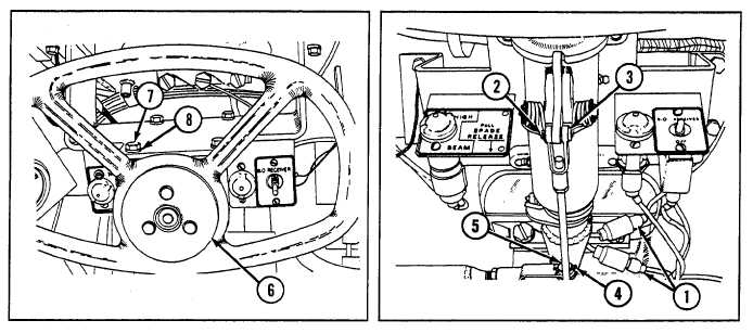
25 Install steering control assembly (6) with four new lockwashers (8) and four screws (7).
26 Install straight pin (5) and new cotter pin (4).
27 Install straight pin (3) and new cotter pin (2).
28 Connect two electrical leads (1).
NOTE
Follow-on maintenance:
Only install or close items necessary to gain access to area of
linkage requiring removal.
Install oddment ray (see paragraph 9-104)
Install toolbox rack (see paragraph 9-103)
Install ammunition rack (see paragraph 9-100)
Install air inlet grilles if removed (see paragraph 9-57)
Install air inlet doors if removed (see paragraph 9-56)
Install cab subfloor plates (see paragraphs 9-1 through 9-23)
Install left-side air cleaner (see paragraph 4-24)
Install powerplant (see paragraph 3-1)
9-73 SERVICE ALIGNMENT OF STEERING CONTROLS AND LINKAGES
THIS TASK COVERS
Alignment
INITIAL SET-UP
Tools:
Material:
Equipment Conditions:
Tool kit, general mechanic's
Adhesive, rubber-base
Powerplant removed (see
(Appendix C, item 53)
(Appendix D, item 3)
paragraph 3-1)
Punches, drive (5) (locating
Batteries removed (see
pins) (Appendix C, item 37)
paragraph 6-4)
9-155