CHAPTER 9: MAINTENANCE OF HULL- AND CAB-RELATED COMPONENTS
TM 9-2350-256-20
9-72 REPLACE/REPAIR STEERING CONTROLS AND LINKAGES-Continued
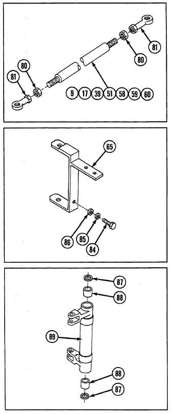
26 If necessary, remove nut (80) and bearing (81) from
each end of connecting links (9, 17, 39, 51, 58, 59, and
60).
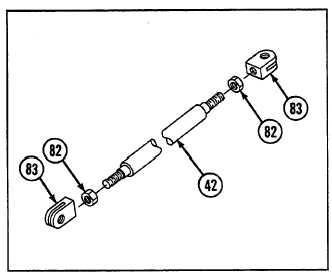
27 If necessary, remove two nuts (82) and two clevis
assemblies (83) from tube assembly (42).
28 Remove mounting bracket (65) by removing three
screws (84), three lockwashers (85), and flat washer
(86).
b. DISASSEMBLY
Remove two seals (87) and two bearings (88) from each of
two bell cranks (89).
c. ASSEMBLY
Install two new seals (87) and two new bearings (88) to
each of two bell cranks (89).
9-150