SECTlON III: SENDING UNITS. WARNING LIGHT SWITCHES, AND
TM 9-2350-256-20
WARNING HORNS
SECTION III: SENDING UNITS, WARNING LIGHT SWITCHES, AND
WARNING HORNS
Para.
Task
Page
6-13
Replace/Repair Switching Relay Box Assembly (Single Voltage Regulator) . . . . . . . . . . ........................................ 6-43
6-14
Replace/Repair/Service Neutral Safety Switch. . . . . . . . . . . . . . . . . . . . . . . . . . . . . . . . . . . . . . . . . . . . . . . . . . . . . . . . . . . . . . . .. 6-46
6-15
Replace/Repair Driver’s Passive Night Viewer Switch and Light and B.O. Receiver Switch and
Light
...................................................................................................................................,..........................
6-47
6-16
Replace/Repair Fire Extinguisher Interlock Switch Assembly . . . . . . . . . . . . . . . . . . . . . . . . . . . . . . . . . . . . . . . . . . . . . . . . . . . . . . . . . . . . . . . . .
6-49
6-17
Replace/Repair Power Control Lever Switch . . . . . . . . . . . . . . . . . . . . . . . . . . . . . . . . . . . . . . . . . . . . . . . . . . . . . . . . . . . . . . . . . . . . . . . . . .
6-49
6-18
Replace Mechanical Transmission Lubrication Oil Low Pressure Switch . . . . . . . . . . . . . . . . ..................................
6-51
6-19
Replace Transmission Oil Pressure Sending Unit, Oil Temperature Sending Unit and Switch............... 6-51
6-20
Replace/Repair External Vehicle Warning Horn . . . . . . . . . . . . . . . . . . . . . . . . . . . . . . . . . . . . . . . . . . . . . . . . . . . . . . . . . . . . . . . . ..
6-52
6-21
Replace/ Repair Power-plant Warning Horn . . . . . . . . . . . . . . . . . . . . . . . . . . . . . . . . . . . . . . . . . . . . . . . . . . . . . . . . . . . . . . . . . . . . . . . .
6-51
6-23
Replace Engine Oil Temperature Sending Unit, Engine Oil Pressure Sending Unit, and Switches . . . . . . . .. 6-55
6-13 REPLACE/REPAIR SWITCHING RELAY BOX ASSEMBLY (SINGLE VOLTAGE
REGULATOR)
THIS TASK COVERS
a. Removal
b. Disassembly
c. Assembly
d. Calibration
e. Installation
INITIAL SET-UP
Tools:
Tool kit, general mechanic’s (Appendix C, item 53)
Parts:
•Gaskets (2) (Appendix G, item 66)
•Gasket (Appendix G, Item 87)
•Gasket (Appendix G, item 72)
•Lockwashers (2) (Appendix G, item 103)
•lockwashcrs (4) (Appendix G, item 106)
•Lockwashers (5) (Appendix G, item 108)
Parts-Continued:
•Lockwashers (12) (Appendix G, item 126)
•Lockwasher (Appendix G, item 127)
•Lockwashers (8) (Appendix G, item 128)
•Lockwashers (30) (Appendix G, item 130)
Equipment Condition:
Left-rear air inlet doors removed (see
paragraph 9-56)
Be certain MASTER switch is OFF when working on electrical system to avoid electrical shock and burns.
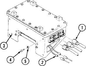
a. REMOVAL
1
Disconnect three connectors (1).
2
Disconnect two leads (2).
3
Remove switching relay box (3) by removing five
screws (4) and five lockwashers (5).
Change 1
6-43