TM 9--2350--292--20--1
0245 00--2
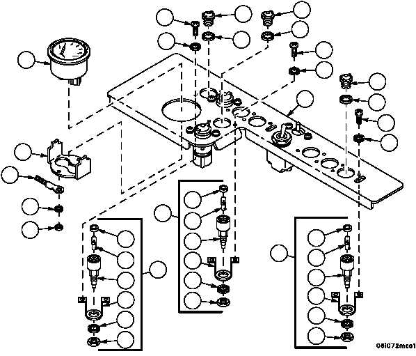
HYDRAULIC CONTROL PANEL REPAIR -- CONTINUED
0245 00
Disassembly
1. Remove two nuts (6), ground wire (7), two lockwashers (8), temperature indicator bracket (9) and temperature
indicator (10) from hydraulic control panel (11). Retain attaching hardware for installation.
NOTE
There are nine indicator lights on the hydraulic control
panel. Seven are removed and disassembled in the
same manner. Perform steps 2 and 3 for removal and
disassembly of these indicator lights.
2. Remove lens (12), gasket (13), two screws (14), two lockwashers (15) and indicator light assembly (16) from hy-
draulic control panel (11). Discard lockwashers and gasket.
3. Remove electrical bondnut (17), lockwasher (18), retaining strap (19), gasket (20) and LED (21) from socket (22).
Discard lockwasher and gasket.
6
7
8
9
10
14
15
12
13
12
13
14
15
12
13
14
15
11
20
21
22
19
18
17
16
16
20
21
22
19
18
17
16
20
21
22
19
18
17