TM 9--2350--292--20--1
0245 00--5
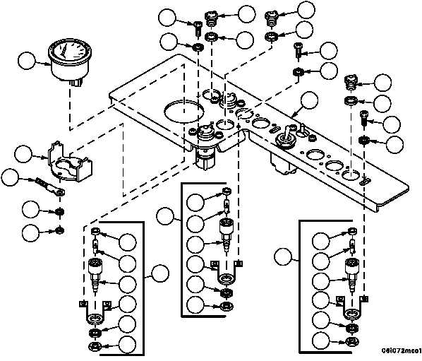
HYDRAULIC CONTROL PANEL REPAIR -- CONTINUED
0245 00
Assembly--Continued
NOTE
There are nine indicator lights on the hydraulic control
panel. Seven are assembled and installed in the same
manner. Perform steps 5 and 6 for assembly and instal-
lation of these indicator lights.
5. Install LED (21), new gasket (20), retaining strap (19), new lockwasher (18) and electrical bondnut (17) on socket
(22).
6. Install indicator light assembly (16), new gasket (13) and lens (12) on hydraulic control panel (11) with two screws
(14) and two new lockwashers (15).
7. Install temperature indicator (10) and temperature indicator bracket (9) on hydraulic control panel (11) with two
lockwashers (8), ground wire (7) and two nuts (6).
6
7
8
9
10
14
15
12
13
12
13
14
15
12
13
14
15
11
20
21
22
19
18
17
16
16
20
21
22
19
18
17
16
20
21
22
19
18
17