TM 9--2350--292--20--1
0248 00--4
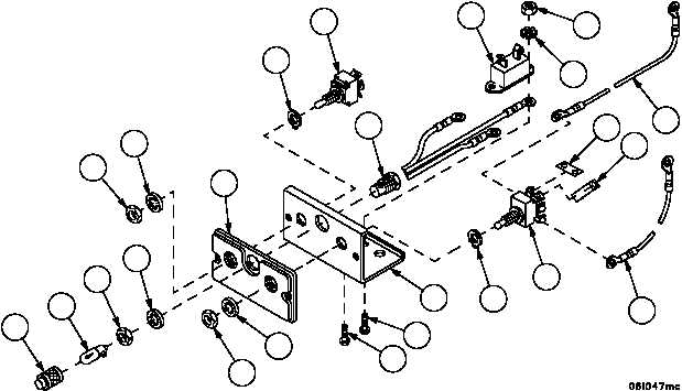
PERSONNEL HEATER CONTROL BOX ASSEMBLY REPAIR -- CONTINUED
0248 00
Disassembly--Continued
9. Disconnect one end of cable assembly 4W147--2 (30) from pin 13 of heater switch (27), the other end from pin 19
of heater control switch (28) and remove.
10. Disconnect one end of cable assembly 4W147--1 (31) from pin 17 of circuit breaker (19), the other end from pin
15 of heater control switch (28) and remove.
11. Remove nut (32), lockwasher (33), ground wire of indicator lamp assembly (29), screw (34), screw (35) and circuit
breaker (19). Discard lockwasher.
NOTE
Retain switch and indicator lamp assembly mounting
hardware. Hardware is part of component and required
for installation.
12. Remove nut (36), lockwasher (37), key washer (38) and heater switch (27) from panel (39).
13. Remove nut (40), lockwasher (41), key washer (42) and heater control switch (28) from panel (39).
14. Remove lens (43), lamp (44), nut (45), lockwasher (46), indicator lamp assembly (29) and face plate panel (47)
from panel (39).
15. Remove jumper (48) between pins 21 and 18 of heater control switch (28).
16. Remove jumper (49) between pins 21 and 14 of heater control switch (28).
17. Inspect parts for damage and replace as required.
Figure 68
36
37
39
42
28
30
32
33
19
29
27
38
47
41
40
35
34
31
43
44
45
46
49
48