TM 9--2350--292--20--2
0389 00--6
TORSION BARS AND TORSION BAR ANCHORS REPLACEMENT --
CONTINUED
0389 00
Installation--Continued
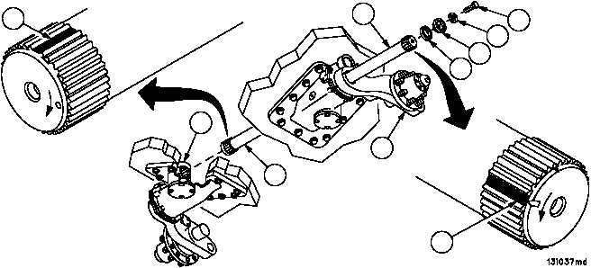
8. Install torsion bar (6) through arm assembly (5), rotate torsion bar (6) in direction of arrow on torsion bar outer end
until blank serration (15) on inner end of torsion bar (6) aligns with blank serration in torsion bar anchor (12).
9. Align blank serration (16) on arm assembly end of torsion bar (6) with blank serration in arm assembly (5) by ro-
tating arm assembly (5) until V--notch on torsion bar (6) aligns with V--notch on arm assembly (5). Push firmly
against torsion bar (6) until torsion bar (6) is fully seated in torsion bar anchor (12).
10. Remove slide puller and torsion bar adapter from torsion bar (6).
11. Install spacer ring (4) and end plug (3) on arm assembly (5) with screw (1) and new lockwasher (2). Torque screw
(1) to 75--100 lb--ft (102--136 NSm).
Figure 178
1
2
3
4
6
5
12
6
16
15
NOTE
FOLLOW--ON MAINTENANCE:
Install subfloor plates, if removed (WP 0454 00)
Install powerpack, if removed (WP 0188 00)
Install main winch and spade, if removed (WP 0497 00)
Connect track, if disconnected (TM 9--2350--292--10)
Connect adjusting link, if disconnected
(WP 0392 00 old configuration)
(WP 0393 00 new configuration)
Connect shock absorber, if disconnected (WP 0412 00)
Install solid rubber wheel (WP 0386 00)
Raise and lock spade in stowed position, if lowered
(TM 9--2350--292--10)
END OF TASK