TM 1-1680-320-13&P
0034 00
NOTE
Ensure cam lobes are not engaging limit switch actuators during testing. Limit
switches are normally closed.
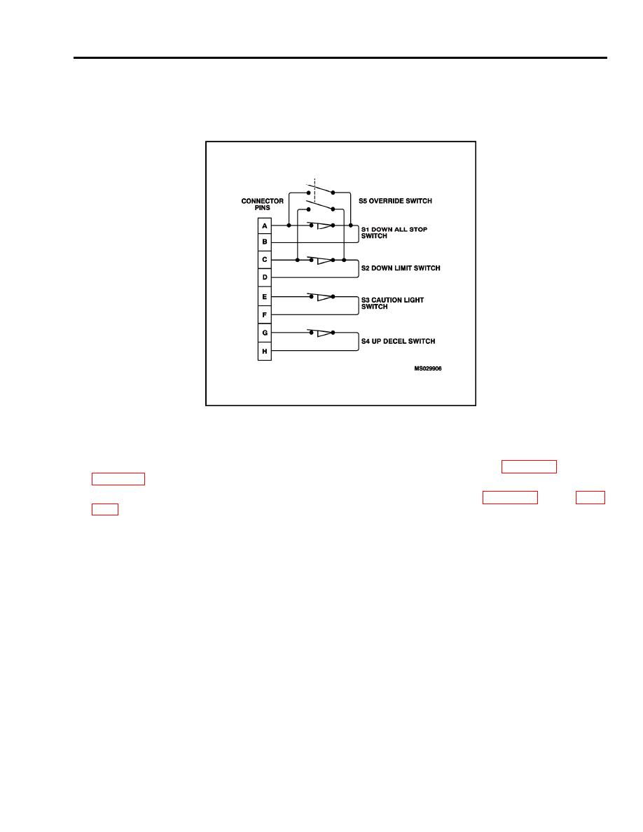
2. Connect multimeter to pins A and B of drive assembly electrical connector; there will be continuity.
3. Press down on limit switch S1 actuator; continuity will be broken, release actuator.
4. If continuity is not present in accordance with step 2, replace limit switch drive assembly, 0034 00-3 through
5. If continuity is present in accordance with step 3, replace limit switch drive assembly, 0034 00-3 through 0034
6. Repeat steps 2 through 5 for limit switch S2, using pins C and D.
7. Repeat steps 2 through 5 for limit switch S3, using pins E and F.
8. Repeat steps 2 through 5 on limit switch S4, using pins G and H.
0034 00-7


