TM 9-2350-256-20-1
0002 00
Internal ComponentsContinued
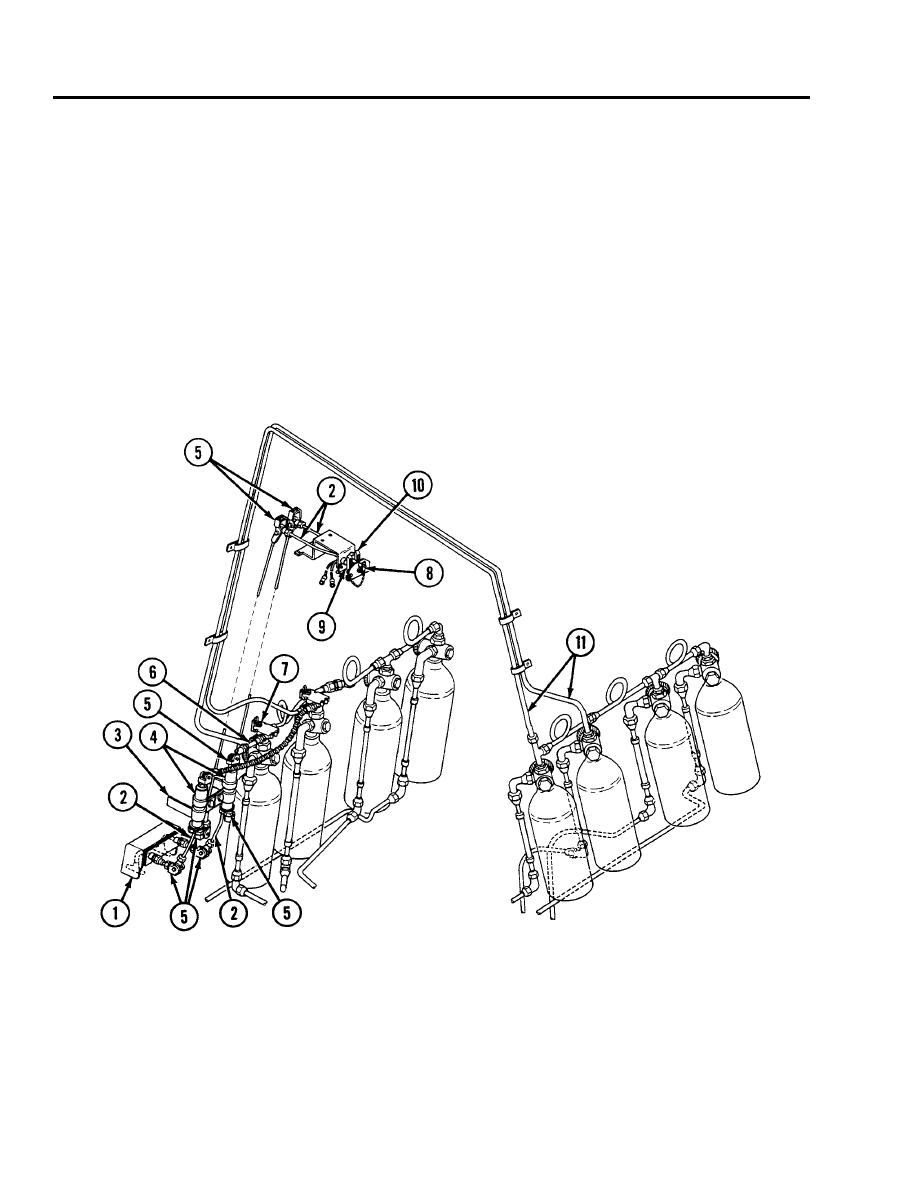
Fixed Fire Extinguisher System--Schematic Diagram
The following two illustrations provide an overview of the fixed fire extinguisher system lines and nozzles associated with WP
0400 00 thru 0403 00.
1.
Outside remote control box
2.
Conduit assembly, control box to dual-pull mechanism
3.
Dual-pull mechanism mounting bracket, left- and right-side
4.
Dual-pull mechanism
5.
Cable pulley assembly
6.
Dual-pull mechanism to cylinder assembly
7.
Control valve
8.
Engine shutoff
9.
Pull handle, right-side
10.
Pull handle, left-side
11.
Rubber pressure hose
Figure 12. Fixed Fire Extinguisher System (1 of 2).
0002 00-14


