TM 9-2350-256-20-1
0002 00
Internal ComponentsContinued
Stowage--Schematic Diagram
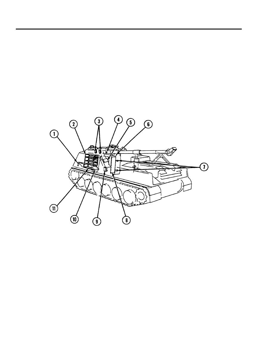
The following two illustrations are of the right and left interior stowage areas associated with WP 0382 00 thru 0394 00.
1.
Hose rack and retainers
2.
Flasher light case and brackets
3.
Caliber .50 barrel straps
4.
M16 strap
5.
Hand grenade boxes
6.
Rocket ammunition stowage box assembly
7.
Stowage straps
8.
Hand fire extinguisher bracket (right side)
9.
Liquid container stowage basket
10.
Stowage baskets (under floor)
Figure 14.
Left Rear View.
0002 00-18


