TM 9-2350-256-20-1
UNIT MAINTENANCE
RECOVERY VEHICLE, FULL TRACKED: MEDIUM, M88A1
NSN 2350-00-122-6826, EIC AQA
COOLING SYSTEM THEORY OF OPERATION
Cooling System
Air Cooling
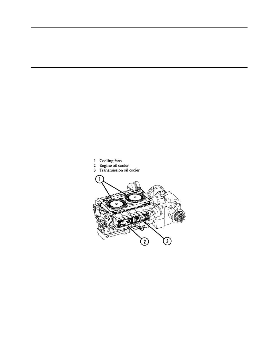
Air for cooling enters the engine compartment through the grille doors. The top of the engine is shrouded and encloses two
gear-driven, axial-flow cooling fans (1) which draw the air through the cylinder fins and oil coolers and discharge the hot air
vertically from the shroud. Sheet metal baffles and deflectors direct the flow of cooling air across the cylinders.
The cooling fans (1) are attached to hubs and are mounted on shafts which are driven by the engine-driven fan drive clutch
assembly.
The fan drive shaft and gear shift are driven by a horizontal drive shaft.
The fan clutch is oil cooled. The fan clutch drive and driven disks are loaded by the centrifugal action of clutch balls and springs
housed in the clutch assembly. The balls and springs are in the driven member and apply upward force to the clutch disks. The
clutch oil enters the fan drive vertical shaft from the fan drive housing through an annular groove in the shaft. The depth of the
groove controls the amount of oil flow. The oil flows through a central hole in the shaft to a distributor where it is dispersed to
the two ball bearings and the clutch disks. The oil moves between the clutch disks by centrifugal action and drains back through
the fan drive housing into the engine oil pan. The fan clutch is designed to slip under deep water fording conditions where the
resistance of the water exceeds the friction of the clutch.
Figure 1.
Cooling System.
Oil Cooling
Two engine oil coolers (2) and two transmission oil coolers (3) are mounted on the sides of the engine above the cylinders. The
cooling fans (1) draw air through the oil cooler cores to cool the oil being circulated within the coolers.
END OF WORK PACKAGE
0007 00-1/2 blank


