TM 9-2350-256-20-1
0046 00
CORRECTIVE ACTION Continued
4.
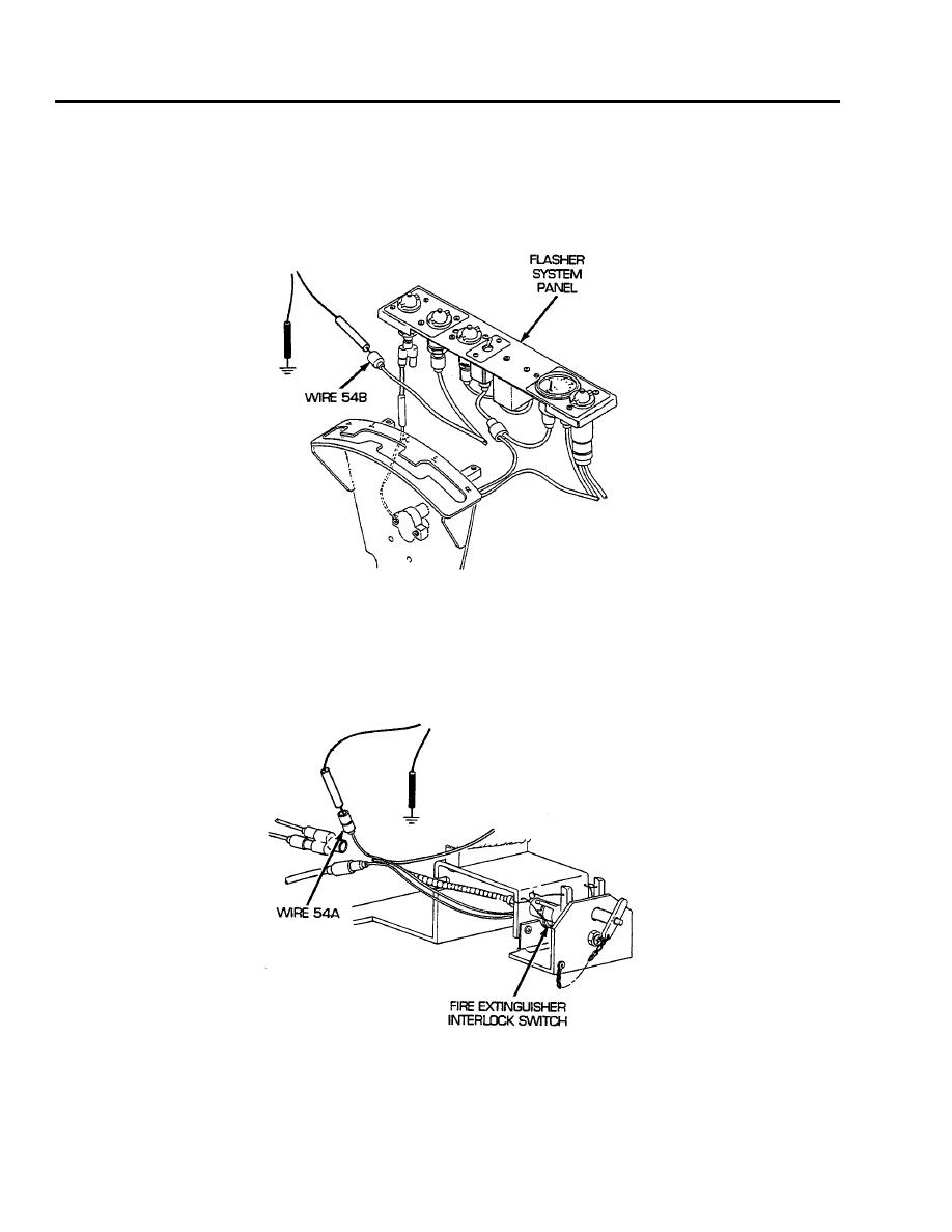
Reconnect wire 54B of flasher system panel wiring harness to diode lead assembly connector. Dis-
connect wire 54B/GND of diode assembly from connector. Place red lead of multimeter on pin of
connector and black lead to ground. Turn MASTER and FUEL SHUTOFF switches OFF. If voltage is
present, repair/replace wire 54B/GND of diode lead assembly from connector to GND (see WP 0238
00). If voltage is not present, repair/replace connector of diode lead assembly (see WP 0238 00).
5.
Reconnect wire 54B of flasher system panel wiring harness to connector at fire extinguisher interlock
switch. Disconnect flasher system panel wiring harness Y-connector from wire 54A of fire extinguisher
interlock switch assembly. Place red lead of multimeter in wire 54A and black lead to ground. Turn
MASTER and FUEL SHUTOFF switches ON, release fire extinguisher interlock switch and check for
voltage. Turn MASTER, FUEL SHUTOFF, and fire extinguisher interlock switches OFF. If voltage is
present, replace connector of flasher system panel wiring harness (see WP 0197 00). If voltage is not
present, troubleshoot fuel shutoff solenoid circuit.
END OF WORK PACKAGE
0046 00-4


