
TM 9-2350-256-20-1
0059 00
CORRECTIVE ACTION Continued
8.
Reconnect wire 65A to APU START switch side of circuit breaker. Disconnect wire 65 from panel
connector side of 15 A circuit breaker. Place red lead of multimeter in wire 65 and black lead to ground.
Turn MASTER and PREHEAT switches ON, and check for voltage. Turn MASTER and PREHEAT
switches OFF. If voltage is not present, go to step 9. If voltage is present, replace 15 A circuit breaker
(see WP 0438 00).
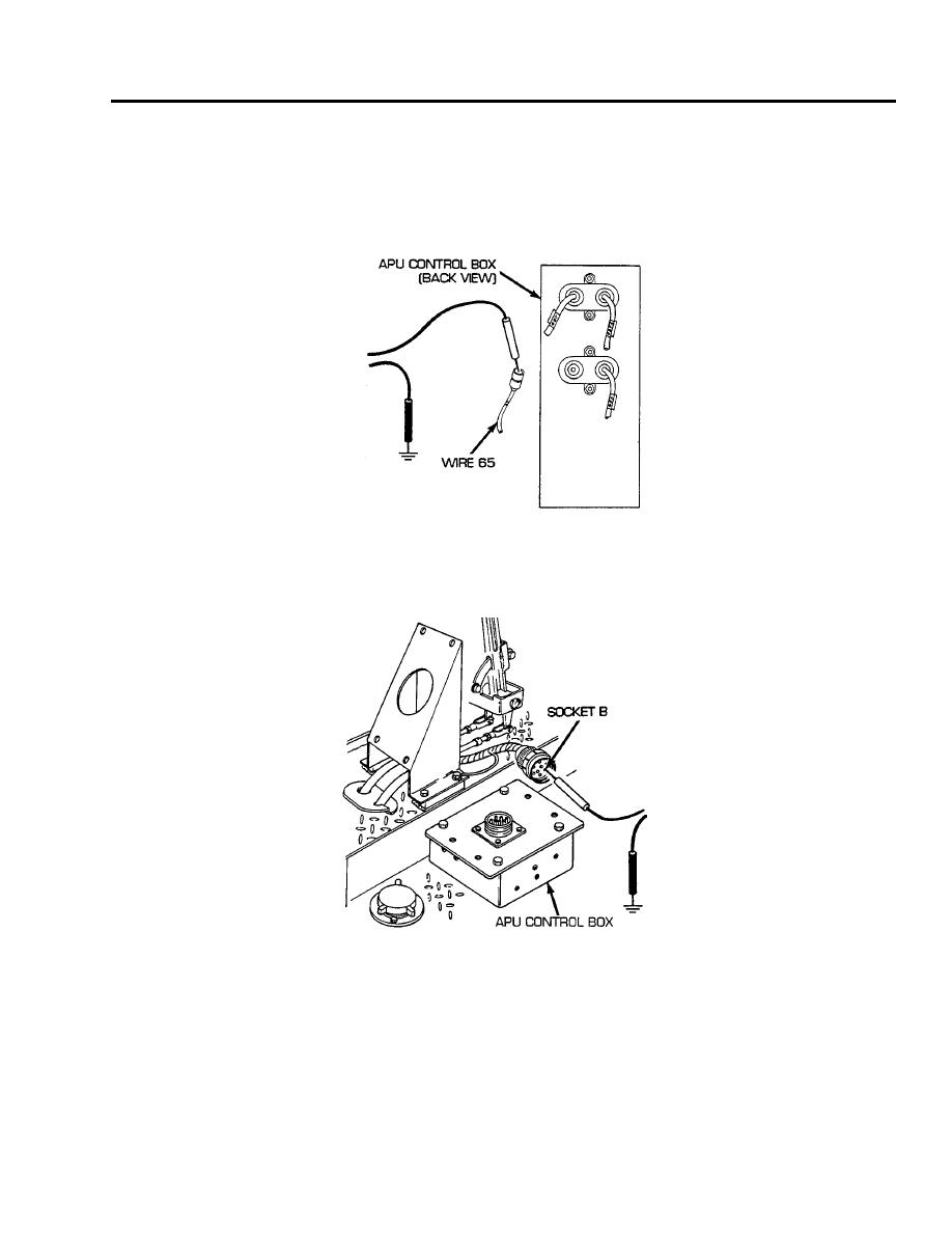
9.
Disconnect APU control box to foot dimmer switch and bulkhead wiring harness from APU control
box. Place red lead of multimeter in socket B of wire 65 and black lead to ground. Turn MASTER
and PREHEAT switches on, and check for voltage. Turn MASTER and PREHEAT switches OFF. If
voltage is present, repair/replace wire 65 of APU control box. If voltage is not present, go to step 10.
0059 00-7
