
TM 9-2350-256-20-1
0059 00
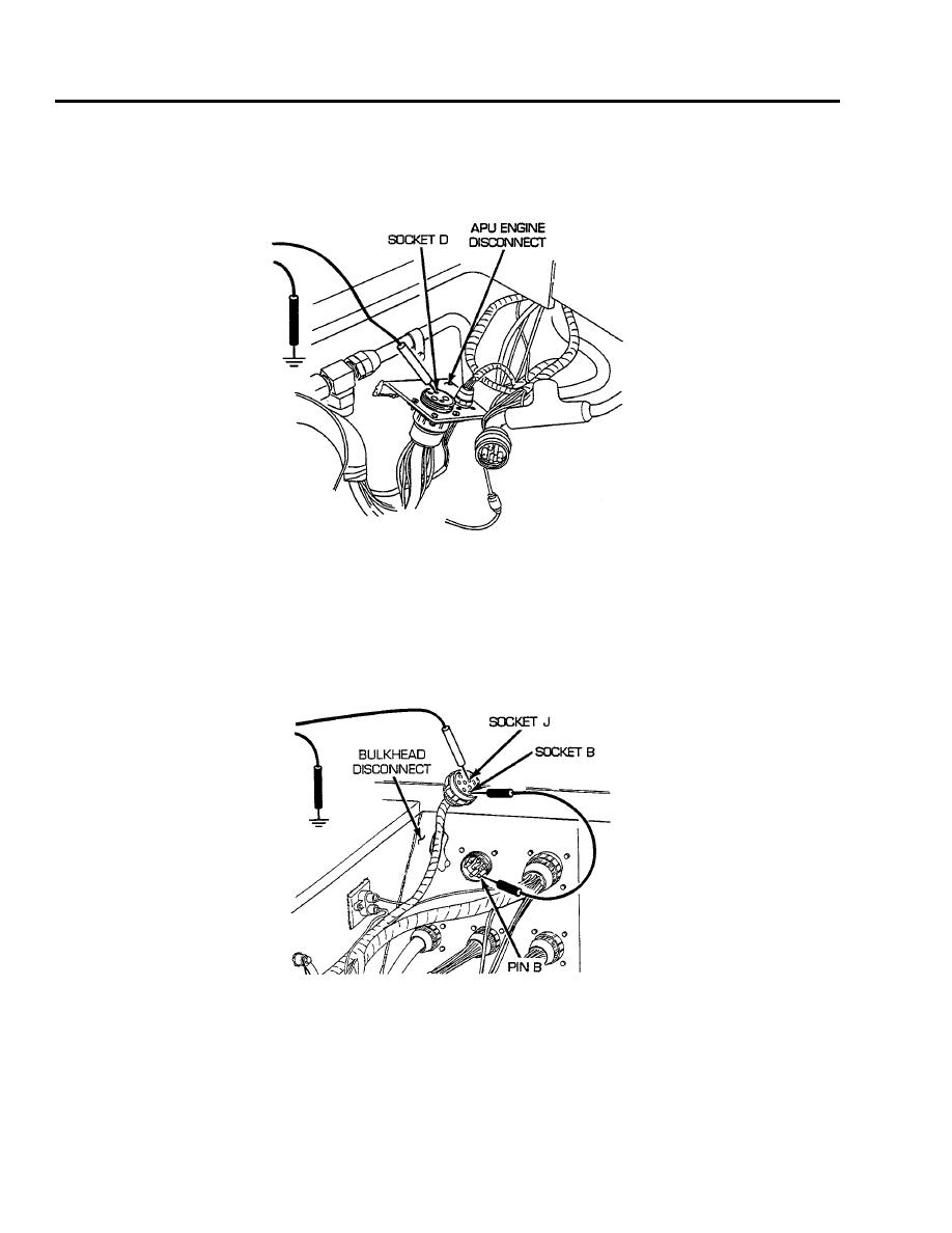
CORRECTIVE ACTION Continued
3.
Place red lead of multimeter in socket D of wire 487 and black lead to ground. Turn MASTER and
PREHEAT switches ON and check for voltage. Turn MASTER and PREHEAT switches OFF. If
voltage is present, notify Direct Support Maintenance. If voltage is not present, go to step 5.
4.
Reconnect bulkhead to APU, master relay, and rigger's lights wiring harness to APU engine disconnect.
Open air inlet doors (see TM 9-2350-256-10). Disconnect bulkhead to APU, master relay, and rigger's
lights wiring harness from bulkhead disconnect. Place a jumper wire from pin B to socket B. Place
red lead of multimeter in socket J of wire 65 and black lead to ground. Turn MASTER and PREHEAT
switches ON and check for voltage. Turn MASTER and PREHEAT switches OFF. If voltage is present,
repair/replace wire 65 of APU control box to foot dimmer switch and bulkhead wiring harness (see WP
0228 00 for dual voltage; 0229 00 for single voltage). If voltage is not present, reconnect bulkhead to
APU, master relay, and rigger's lights wiring harness to bulkhead disconnect and go to step 5.
0059 00-4
