TM 9-2350-256-20-1
0090 00
CORRECTIVE ACTION Continued
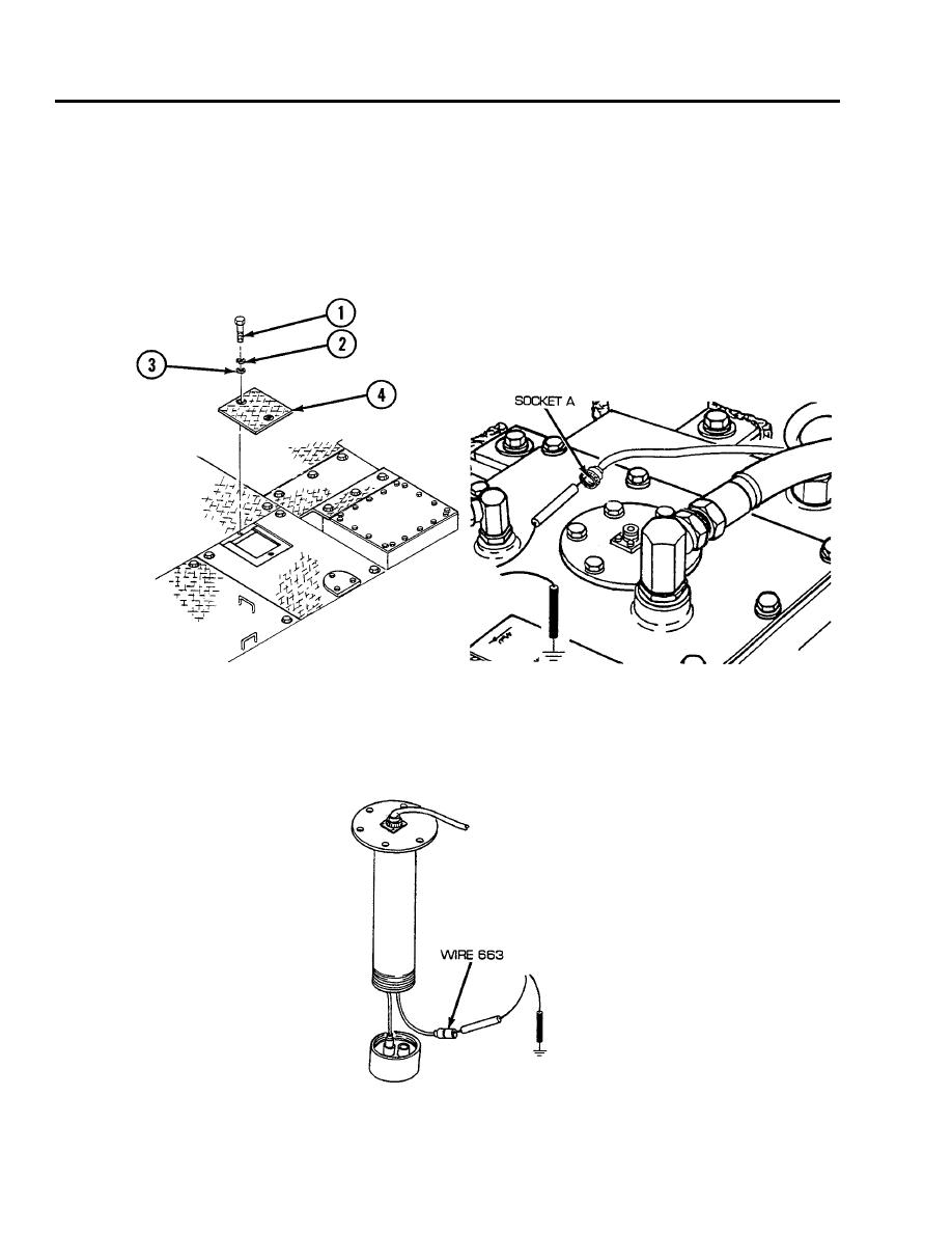
4. Reconnect flasher system panel wiring harness to lamp socket. Remove two screws (1), two lock-
washers (2), two flat washers (3), and rear intermediate right access floor plate (4). Disconnect flasher
system panel wiring harness at hydraulic reservoir disconnect. Place red lead of multimeter in socket
A of wire 663 and black lead to ground. Turn MASTER switch on, place power control lever switch
in ON position, and check for voltage. Turn MASTER switch and power control lever switch OFF. If
voltage is present, go to step E. If voltage is not present, repair/replace wire 663 of flasher system panel
wiring harness from hydraulic oil high temperature lamp to hydraulic reservoir disconnect (see WP
0197 00).
5.
Reconnect flasher system panel wiring harness to hydraulic reservoir disconnect. Disconnect wire
663 from high temperature switch on hydraulic reservoir. Place red lead of multimeter in wire 663 and
black lead to ground, turn MASTER switch on, place power control lever switch in ON position, and
check for voltage. Turn MASTER switch and power control lever switch OFF. If voltage is present,
replace high temperature switch (see WP 0425 00). If voltage is not present, repair/replace wire 663 of
hydraulic oil temperature transmitter wiring harness (see WP 0237 00).
END OF WORK PACKAGE
0090 00-4


