TM 9-2350-256-20-2
0275 00
WARNING
Lift arm sufficiently to take weight off torsion bar. Securely block arm to prevent arm from falling after
bar has been removed.
3.
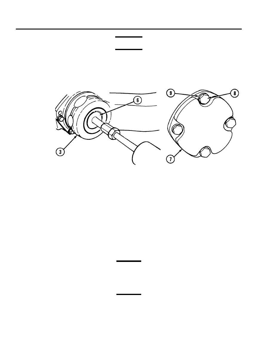
Remove torsion bar (6) by using adapter and puller.
4.
Remove torsion bar anchor cover plate (7) by removing four screws (8) and four lockwashers (9).
Remove and discard gasket (11) from torsion bar anchor cover plate (7).
5.
6.
Remove torsion bar anchor (10).
Installation
NOTE
During installation, place the torsion bar anchor (10) in the housing so that the word "FRONT" is toward
the front of the vehicle and the cover tangs enter the spanner holes.
Coat torsion bar anchor (10) and anchor splines with grease and install torsion bar anchor.
1.
Install torsion bar anchor cover plate (7) and gasket (11) with four screws (8) and four lockwashers (9). Torque screws to
2.
4050 lb-ft (5468 Nm).
CAUTION
When installing the torsion bar (6), it is not necessary to drive the bar in. When properly aligned, the bar
will slide in easily. If bar is forced, splines will be damaged.
CAUTION
Torsion bars must not be interchanged. Each bar is stamped (on its outside face) with the part number,
and an arrow showing the direction of the loading torque. Before installing a new torsion bar, check
markings on the bar to be certain that the correct bar is used.
0275 00-2


