CHAPTER 13: MAINTENANCE OF APU
TM 9-2350-256-20
13-7 REPLACE/REPAIR APU CONTROL BOX-Continued
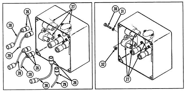
7
Disconnect six connectors (26) from three circuit breakers (27) and remove three lead assemblies (28) and APU
control box wiring harness (29).
8
Remove three circuit breakers (27) by removing two screws (30), two lockwashers (31), and two nuts (32) from
each.
9
Remove APU generator switch (23) and three switches (25) by removing eight screws (33), eight lockwashers (34),
and two switch guards (35).
10
Remove oil pressure indicator (21) by removing two nuts (36), two lockwashers (37), and bracket (38).
11
Remove two indicator lights (19) by removing lens (39), gasket (40), two screws (41), and two lockwashers (42)
from each.
NOTE
Remove ID plate (43) only if required.
12
Remove control box ID plate (43) by removing four rivets (44).
13
Disassemble three lead assemblies (28) and APU control box wiring harness (29) (see Chapter 6, Section VII).
13-10