TM 9-2350-256-20
c.
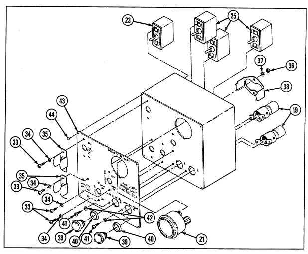
ASSEMBLY
1
Assemble three lead assemblies (28) and APU control box wiring harness (29) (see Chapter 6, Section VII).
2
Install control box ID plate (43) with four new rivets (44), if removed.
3
Install two indicator lights (19) using two new lockwashers (42), two screws (41), gasket (40), and lens (39) for
each.
4
Install oil pressure indicator (21) using bracket (38), two new lockwashers (37), and two nuts (36).
5
Install APU generator switch (23) and three switches (25) using two switch guards (35), eight new lockwashers (34),
and eight screws (33).
6
Install three circuit breakers (27) using two nuts (32), two new lockwashers (31), and two screws (30) for each.
7
Connect six connectors (26) to three circuit breakers (27).
13-11