T M 9 - 2 3 5 0 - 2 5 6 - 2 0
J-5 LUBRICATION INSTRUCTIONS-Continued
c. SERVICE FROM ENGINE COMPARTMENT-Continued
5
Brake slack adjuster lever.
6
a.
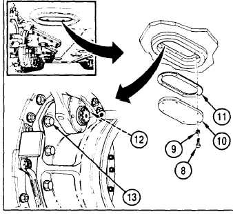
Reemove six screws (8) and six lockwashers (9)
which secure brake adjustment access cover
(10) to bottom of hull.
b.
Remove access cover (10) and gasket (11).
c.
Lubricate brake slack adjuster lever with GAA
through fitting (12).
d.
Install gasket (11), access cover (10), six screws
(8), and lockwashers (9). Repeat procedure for
other side of vehicle.
Output reduction drives drain
NOTE
Each time transmission is drained,
approximately five gallons of oil remain in
each output reduction assembly. Drain oil
each time transmission is flushed.
APPENDIX J: LUBRICATION INSTRUCTIONS
a.
Remove six screws (8) and six lockwashers (9) which secure brake adjustment access cover to bottom of
hull.
b.
Remove access cover (10) and gasket (11). Remove bolt (13) located at bottom centerline of saddle
mounting face (this is the same bolt that secures end of brake stop to assembly). After oil has drained,
install bolt.
c.
Install gasket (11), access cover (10), six screws
(8), and lockwashers (9). Repeat procedure for
other side of vehicle.
7
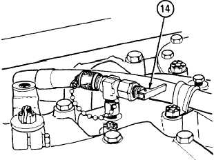
AOAP-transmission. For active units, obtain oil
samples from transmission (14) every 25 hours of
operation or 30 days (whichever comes first). Send
these samples to the nearest AOAP laboratory.
Refer to TB 43-0210 for sampling instructions. If or
when AOAP laboratory support is unavailable,
hard-time intervals will apply.
J-30
Change 1