SECTION V: TROUBLESHOOTING
TM 9-2350-256-20
WARNING
Remove all jewelry such as rings, dog tags,
bracelets, etc. If jewelry contacts a metal
surface a direct short may result in instant
heating of tools, damage to equipment, and
injury or death to personnel.
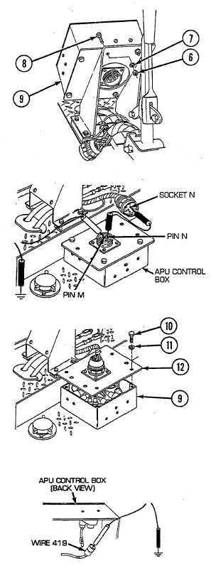
D Remove four nuts (6), four lockwashers (7), and four
screws (8), and release APU control box (9) from
mounting bracket. Place a jumper wire from pin N to
socket N. Place red lead of multimeter on pin M of wire
420 and black lead to ground. Turn MASTER and APU
FUEL SHUTOFF switches ON, and check for voltage.
Turn MASTER and APU FUEL SHUTOFF switches OFF.
If voltage is present, go to step K. If voltage is not
present, go to step E.
E Reconnect APU control box to foot dimmer switch and
bulkhead wiring harness to APU control box. Remove
four nuts (10) and four lockwashers (11), and pull rear
panel (12) from APU control box (9). Disconnect wire
419 from panel connector side 15 A circuit breaker.
Place red lead of multimeter in wire 419 and black lead
to ground. Turn MASTER switch on and check for
voltage. Turn MASTER switch OFF. If voltage is
present, go to step F. If voltage is not present,
repair/replace wire 419 of APU control box wiring harness
(see paragraph 13-7).
2-193