SECTION V: TROUBLESHOOTING
TM 9-2350-256-20
WARNING
Remove all jewelry such as rings, dog tags,
bracelets, etc. If jewelry contacts a metal
surface a direct short may result in instant
heating of tools, damage to equipment, and
injury or death to personnel.
G
Open
air
inlet
doors
(TM
9-2350-256-10).
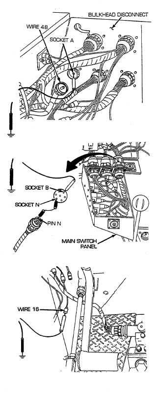
Reconnect switch panel to gage panel and
miscellaneous switches wiring harness to main
switch panel. Disconnect wire 48 pin A from
bulkhead to master relay wiring harness. Place
red multimeter lead in socket A and black lead to
ground. Turn MASTER switch on and check for
voltage. If voltage is present, repair/replace
switch panel, radio, and bilge pump to bulkhead
wiring harness (see paragraph 6-53). If voltage is
not present, troubleshoot master relay circuit (see
paragraph 2-19, master relay fails to operate).
H
Place a jumper wire from pin N to socket N.
Place red lead of multimeter in socket B of wire 16
and black lead to ground. Turn MASTER switch
on, UNLOCK and move main lighting switch in
SER. DRIVE position, and check for voltage.
Turn MASTER and main lighting switches OFF. If
voltage is present, go to step I. If voltage is not
present, go to step J.
I
Reconnect switch panel to gage panel and
miscellaneous switches wiring harness to main
switch panel. Disconnect wire 16 of switch panel
to gage panel and miscellaneous switches wiring
harness from headlight and dimmer switch wiring
harness. Place red lead of multimeter on male
connector of wire 16 and black lead to ground.
Turn MASTER switch on, UNLOCK and move
main lighting switch in SER. DRIVE position, and
auxiliary switch in any position other than PARK
and check for voltage. Turn MASTER and main
lighting switches OFF. If voltage is present,
repair/replace wire 16 of headlight and dimmer
switch wiring harness (see paragraph 6-65). If
voltage is not present, repair/replace wire 16 of
switch panel to gage panel and miscellaneous
switches wiring harness (see paragraph 6-55 for
dual voltage; 6-56 for single voltage).
2-277