CHAPTER 1: INTRODUCTION
TM 9-2350-256-20
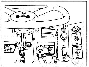
1-27 EXHAUST SMOKE GENERATING SYSTEM
NOTE
The following callout is found in Figure 1-16.
The exhaust smoke generating system consists of
1 Switch
solenoid valves, switch assemblies, shutoff valve,
indicator light, mounting brackets, fuel hose
assemblies, electrical leads, and attaching parts.
The solenoid valves and fuel tube assemblies are
attached to the rear of the engine. Fuel to operate the
smoke generating system is taken from the main fuel
supply at the front of the engine.
The switch (1) to operate the smoke generating system
is installed in the driver's compartment and the
commander's station, and is connected to the main
wiring harness using electrical leads provided in the
smoke generating system kits.
The smoke generating system uses the engine fuel
pump to supply diesel fuel, from the vehicle fuel tanks,
to two solenoid valves mounted at the rear of the
Figure 1-16. Exhaust Smoke Generating System.
engine. When the solenoid valves are energized
(opened), they allow diesel fuel to be sprayed into the exhaust system. The fuel vaporizes and exits together with the
engine exhaust gases. The fuel vapor cools on contact with the moving exhaust air and condenses to form a dense
smoke screen. The electrical power to energize the solenoid valves is supplied by the warning indicator and warning
horn systems. The warning horn will not sound unless the engine is running, and connection to this system prevents
accidental activation of the smoke generating system when the engine is not running.
The manual fuel shutoff valve can be used to determine if the smoke produced is from a malfunctioning engine, or from
the smoke generating system.
1-28 DEEP WATER FORDING KIT
a. GENERAL
The deep water fording kit as installed on the M88A1 permits fording to a maximum depth of 8 ft, 6 in. (2.59 m).
The design of the deep water fording equipment permits the vehicle to be completely operable on land or in
water, providing maximum depth is not exceeded.
b. ENGINE EXHAUST
The engine exhaust system for deep water fording consists of a series of pipes to provide the proper venting of the
exhaust for the right and left banks of the engine. A flexible, bellowed-type pipe is clamped to the engine exhaust outlet.
Utilizing a slip joint, each pipe is attached to the main engine exhaust pipe, which ducts the exhaust gases through the
rear engine deck. To each engine exhaust pipe, a 4-1/2-in.- (114-mm-) diameter pipe, which extends above the specified
depth, is clamped and sealed. Two clamps, bolted to the engine deck, are used to hold the system in proper position.
1-34