CHAPTER 1: INTRODUCTION
TM 9-2350-256-20
1-21 WINCHES, SPADE ASSEMBLY, AND HOISTING BOOM--Continued
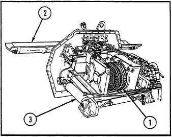
b. SPADE ASSEMBLY
1 Main winch
2 Spade
The spade (2) is mounted to the vehicle nosepiece by
3 Hydraulic cylinders
two trunnion-mounted arms. The arms are operated
by hydraulic cylinders (3) from within the winch
compartment. When not in use, the spade is secured in
a raised position by a hydraulically activated, spring-
loaded spade lock.
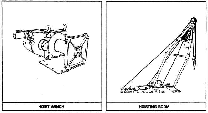
c. HOIST WINCH
The hoist winch is mounted in the winch compartment
and is gear-driven by a hydraulic motor. The winch is
capable of hoisting a maximum load of 50,000 lb
(22,680 kg) with a four-part line, using a 5/8-in. (15.88-
mm) steel cable. The hoist winch is wound with 200 ft
(61.0 m) of this steel cable.
d. HOISTING BOOM
The hoisting boom is a tubular, modified A-frame, and
is pivot-mounted to the top front of the vehicle. The
Figure 1-13. Main Winch and Spade Assembly.
boom is raised or lowered by two hydraulically
operated boom cylinders. In operating position, the boom is supported by a stayline cable secured to crankarms
located at the rear of the hull. The crankarms control the live-boom movement by means of hydraulically
operated stayline cylinders. In lowered position, the boom is secured on the boom support assembly by a boom
travel lock. The hoisting boom is used in conjunction with the hoist winch.
1-30


