TM 9-2350-256-20
CHAPER 1: lNTRODUCTION
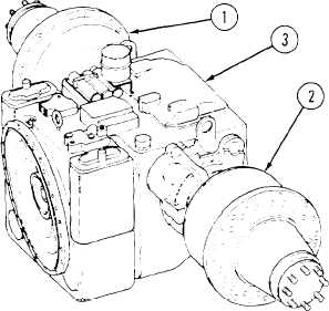
1 - 1 8 T R A N S M I S S I O N A N D O U T P U T R E D U C T I O N D R I V E S - C o n t i n u e d
b. HYDRAULIC AND LUBRICATION SYSTEM
Functions:
Applies force for clutch ranges
Power transmitting medium in torque converter
Lubricant For entire transmission
Cooling medium for entire transmission
1 Right output reduction drive
2
Left output reduction drive
3 Cross-drive transmission
Figure 1-10. Transmission and
Output Reduction Drives.
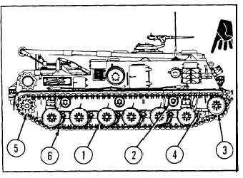
1 - 1 9 T R A C K S A N D S U S P E N S I O N S Y S T E M S
NOTE
1 Roadwheels
2 Track support rollers
The following callouts are found in Figure 1-11.
3 Compensating idler wheel
4 Compensating idler link
5 Track drive huh and sprocket
The suspension system on each side of the vehicle 6 Track
consists of six pairs of individually sprung roadwheels
(l), three track support rollers (2), a compensating idler
wheel (3), a compensating idler link (4), a track drive
hub and sprocket (5) and a track (6).
Primary springing is accomplished by individual
torsion-bars for each roadwheel. Secondary springing
is accomplished by dual volute bumper springs on
numbers 1 and 6 roadwheels. Bump stop brackets are
welded to the hull over roadwheel numbers 2 through
5 to limit torsion bar windup beyond allowable limits.
Shock absorbers are attached between the first, second,
and sixth roadwheel arms and the hull on each side of
the vehicle. Each track consists of 84 rubber shoe
assemblies. The individual links are held together by
Figure l-11. Tracks and Suspension Systems.
1-28
Change 1