SECTION III: PRINCIPLES OF OPERATION
TM 9-2350-256-20
1-15 MANIFOLD AIR INDUCTION HEATER SYSTEM
NOTE
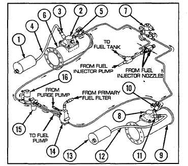
Unless otherwise indicated, the following callouts are found in Figure 1-8.
The left and right intake manifolds (6 and 9), which distribute supercharged air into each bank of cylinders, are equipped
with electrically ignited intake manifold air heaters (2 and 8). The heaters are provided to facilitate engine starting
during cold weather.
The purge pump is operated to obtain 90 psi (621 kPa) in the manifold heater fuel lines. Operation of the heater switch
on the purge pump handle energizes the manifold heater fuel inlet solenoid valve to allow fuel flow to the heater nozzle.
The heater switch also energizes the high-tension coil creating an electrical spark in the manifold, thereby igniting the
sprayed fuel. Continued operation of the purge pump is required to maintain fuel pressure and an effective spray pattern
into the manifold.
A leakoff line is provided to prevent nozzle fouling and is routed into the injector fuel return line. The fuel is burned in the
intake manifold by the ignition of the heater spark plug, which flame-heats the incoming air. This flame-heated air and
the products of combustion are fed directly into the cylinders.
The purge pump line connects to a fuel check and pressure relief valve (14) and pressure regulator valve (see item 20,
Figure 1-7) in the engine. The fuel check and pressure relief valve prevents purged fuel from returning to the tank or to
the purge inlet line.
The fuel check and pressure relief valve (14) ensures the necessary fuel pressure to operate the flame heater spray
nozzles (5 and 10). A manifold heater fuel supply solenoid valve (7) and fuel return solenoid valve (16) close the flame
heater fuel lines when the flame heater switch is off.
The manifold heater fuel return solenoid valve (16) is located at the rear of the engine. The valve is energized at the
same time the ignition unit and heater spark plugs are energized and acts as a check valve to prevent fuel returning from
the injector pump and nozzles from entering the heater fuel tubes.
1
Left manifold heater ignition unit
2
Left manifold air heater
3
Spark plug
4
Ignition unit electrical lead
5
Manifold heater nozzle
6
Left intake manifold
7
Manifold heater fuel supply
solenoid valve
8
Right manifold air heater
9
Right intake manifold
10
Manifold heater nozzle
11
Spark plug
12
Ignition unit electrical lead
13
Right manifold heater ignition unit
14
Fuel check and pressure relief
valve
15
Manifold heater fuel filter
16
Manifold heater fuel return
solenoid valve
Figure 1-8. Manifold Air Induction Heater System
1-23