SECTION III: PRINCIPLES OF OPERATION
TM 9-2350-256-20
1-12
POWERPLANT-Continued
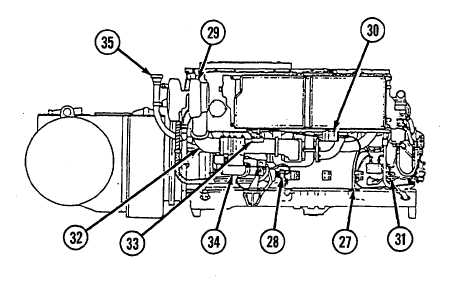
27
Oil level indicator tube
30
Manifold heater ignition unit
33
Intake manifold heater
28
Starter low-voltage module
31
Fuel/water automatic drain control
34
Engine starter
29
Left turbosupercharger
32
Air intake manifold
35
Oil filler tube
Figure 1-6. Engine (4 of 4)
1-13
LUBRICATION SYSTEM
a.
GENERAL
The main pressure oil pump draws oil from the pressure oil pump compartment in the oil pan. This compartment is fed
by the scavenge oil pump which picks up oil from the front end of the oil pan and by oil which drains into the pressure
compartment from the cover of the pressure pump compartment and the reserve compartment. The pressurized oil is
forced through the engine oil coolers and oil filter to the engine oil galleries, bearings, turbosuperchargers, fuel injection
pump, and piston oil sprayer nozzles. These nozzles are located in the crankcase below each cylinder and provide a
continuous oil spray to the pistons and cylinder walls. A pressure regulator valve, located on the right side of the
crankshaft damper and oil filter housing, is influenced by the pressure in the main bearing oil gallery and returns the
incoming, excess, unfiltered oil to the oil pan.
b.
OIL PAN
The oil pan is a one-piece, aluminum-alloy casting divided into a pressure oil pump compartment, oil reserve
compartment, and sump compartment (at the front of the pan). Cored passages from each of the compartments
terminate at a central outlet and permit draining of all of the compartments from a single drainage point. A cored
passage also permits draining the oil coolers and oil filter compartment directly without permitting any sludge to enter the
oil pan. The oil pan is designed to maintain a constant oil level above the main pressure oil pump pickup tube in the
pressure oil pump compartment during vehicle operation, regardless of the angle at which the engine may be inclined.
1-19