SECTION I: FUEL SYSTEM
TM 9-2350-256-20
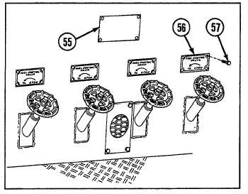
b. INSTALLATION
Install fuel control valves and ID plates in reverse order
using illustration as guide.
NOTE
Follow-on maintenance:
• Close fuel tank drain
valves and fill fuel
tank or turn on fuel
shutoff valves (refer to
TM 9-2350-256-10)
• Install powerplant
(see paragraph 3-1)
4-13 REPLACE FUEL CHECK VALVE
THIS TASK COVERS
a. Removal
b. Installation
c. Test
INITIAL SET-UP
Tools:
Reference:
Tool kit, general mechanic's (Appendix C, item 53)
TM 9-2350-256-10
Parts:
Equipment Condition:
• Bushing (Appendix G, item 5)
Engine deck removed (see paragraph 9-51)
• Lockwashers (2) (Appendix G, item 130)
WARNING
Do not smoke or use open flame when
working on fuel system: explosion may
occur, causing severe injury or death.
NOTE
Turn MASTER switch and fuel pump switch
to OFF position.
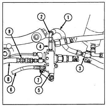
a. REMOVAL
1
Remove fuel inlet hose (1) from elbows (2 and 3).
2
Remove elbow (2) and adapter (4) from fuel check
valve (5).
3
Disconnect fuel pump outlet hose (6) and adapter (7)
from fuel check valve (5).
4
Disconnect manifold heater purge fuel line (8) from
coupling (9).
4—
29