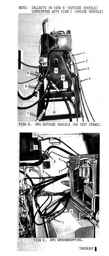
Figure 4-6. Auxiliary power unit test run outside vehicle
(Sheet 2 of 2).
(c) Start the auxiliary
three-minute warmup period
engine and allow a
with no load on the
TM 9-2350-256-34-1
generator or pump. Then check the engine speed
with a hand tachometer or stroboscope. Adjust to
2000 ± 100 rpm, if necessary, in the following man-
ner.
1. Locate the governor speed adjustment
screw on the front of the engine (3, fig. 4-1).
2. Loosen locknut and turn screw slowly
until tachometer or stroboscope reads 2000 ± 100
rpm.
3. Carefully tighten locknut so that the
tachometer or stroboscope reading does not change.
(d) Stop engine, check crankcase oil and fill to
proper level (LO 9-2350-256-12) if required.
(e) Install a pressure gage in the gage port of
the system selector valve on the hydraulic control
panel (subplate) assembly (View A, fig. 2-29).
(f) Start the auxiliary engine, place the
manual shutoff valve in NORMAL OPERATION
position, place the system selector valve in
AUXILIARY position. Check the pressure gage to
confirm a hydraulic load on the auxiliary pump of
2000 ± 50 psi. Adjust the system selector valve
relief valve with the adjusting screw (View A, fig.
2-29), if necessary, to obtain a pressure reading of
2000 ± 50 psi.
(g) Operate the auxiliary engine for 10
minutes with a 2000 ± 50 psi load on the auxiliary
hydraulic pump and no load on the generator.
(h) Check all points for leakage (TM
9-2305-256-20) and correct any other defects.
Return the system selector valve position to the
MAIN position and shut off engine.
(i) Connect a multimeter between the
generator armature terminal and ground (set meter
on DC voltage mode—50 volt range).
(j) DELTED
(k) DELETED
(l) Turn on the generator switch momentarily
and note the generator output voltage on the
multimeter. Voltage should increase slightly when
the generator switch is turned on. If not, remove the
cap from the switching relay box assembly in the
vehicle. Loosen the rheostat locking nut and turn
the adjusting screw slowly clockwise until the
voltage on the multimeter increases slightly. If
voltage does not increase, troubleshoot the system.
I
NOTE
Current limiter rheostat must be
calibrated when the auxiliary power unit
is reinstalled in the vehicle.
(m) Turn off generator.
(n) Turn off engine.
(3) Test inside vehicle.
(a) Make sure that all lines, cables, ac-
cessories and other components are properly in-
stalled, tightened and adjusted. Fill chain case and
crankcase to the proper levels (LO 9-2350-256-12)
if required.
Change 2
4-20.3


