TM 9-2350-256-34-1
(2) Installation. Install the switch panel wiring
harnesses and leads in reverse order of removal, being
careful to match circuit number markers to the correct
receptacles as shown in View C, figure 2-18.
l.
Accessories Panel Wiring Harness and
Leads.
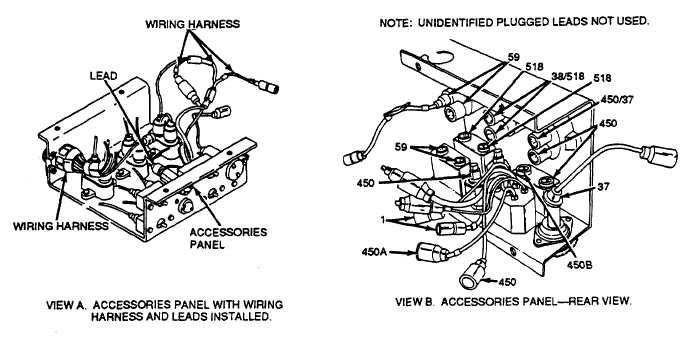
(1) Removal. Prior to removing the accessories
panel wiring harness and leads, remove the accessories
panel from the vehicle (TM 9-2350-256-20). Remove the
wiring harness assembly and leads as shown in figure 2-
19.
(2) Disassembly. Disassemble the wiring harness
assembly and leads as shown in figure 320.
(3) Assembly.
Assemble
the
wiring
harness
assembly and leads in reverse order of disassembly.
Figure 2-19. Accessories panel wiring harness wad leads--removal
and installation (Sheet 1 of 2).
2-42 CHANGE 7