TM 9-2350-256-34-2
(e) Winch braking operation. The main winch brake (fig. 1-6) consists of a circular brake band which
makes contact with the brake drum, and a ratchet and pawl assembly which allows the drum to rotate only in
the clockwise direction. The brake band is held in its normally applied position by a spring-loaded piston in the
brake cylinder. The brake is released by introducing hydraulic fluid into the brake cylinder to overcome the
spring force. When the cabel is inhauled the brake band is in its normally applied position, and the brake
drum, which is not secured to the brake shaft, is held stationary. The two pawls, which are secured directly to
the brake shaft, rotate freely in the counterclockwise direction, thus enabling the cable drum to rotate in the
counterclockwise or INHAUL direction. When the main winch control valve is placed in the HOLD position,
hydraulic motor power is balanced, cable drum rotation ceases, and the brake band remains in its normally
applied position. Any weight on the cable is prevented from slipping by the pawls which engage the ratchet
teeth on the inside diameter of the drum and prevent cable drum movement. The cable is PAID OUT by
introducing hydraulic pressure into the brake cylinder to counteract the piston spring pressure and release the
brake band. The entire brake drum assembly is then free to rotate in the clockwise or PAYOUT direction, even
though the pawls within the brake drum remain engaged with the ratchet teeth.
c. Hoist Winch Assembly.
(1) Detailed description.
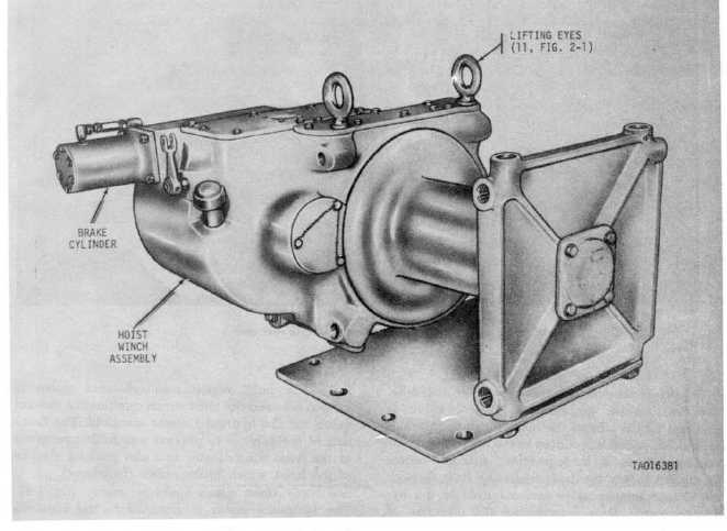
(a) General. The hoist winch assembly (figs. 1-7 and 1-8) is installed in the hull of the vehicle
beneath the crew compartment. It is used for lifting objects and for guiding and hauling the main winch cable.
Major components of the assembly are a winch cable, hoist winch combination control valve, counterbalance
valve, reversible hydraulic motor, brake cylinder and winch assembly complete with an internal brake.
Figure 1-7. Hoist winch assembly-left front view.
1-9


