TM 9-2350-256-34-2
(c) Braking operation. The hoist winch brake (fig. 1-9) consists of a circular brake band which makes
contact with the brake drum, and a ratchet and pawl assembly which allows the drum to rotate only in the
counterclockwise direction. The brake band is held in its normally applied position by a spring-loaded piston in
the brake cylinder. The brake is released by introducing hydraulic fluid into the brake cylinder to overcome the
spring force. When the cable is raised (fig. 1-9), the brake band is in its normal applied position and the brake
drum, which is not secured to the brake shaft, is held stationary. The two pawls, which are secured directly to
the brake shaft, rotate freely in a clockwise direction, thus enabling the cable drum to reel in and raise the
cable. When the control valve is in the HOLD position, hydraulic motor power is cut off, cable drum rotation
ceases, and the brake band remains in its normal applied position. Any weight on the cable is held suspended
by the pawls which engage the ratchet teeth on the inside diameter of the brake drum and prevent cable drum
movement. The cable is lowered by introducing hydraulic pressure into the brake cylinder to counteract the
piston spring pressure and release the brake band. The entire brake drum assembly is then free to rotate in a
counterclockwise direction even though the pawls within the brake drum remain engaged with the ratchet teeth.
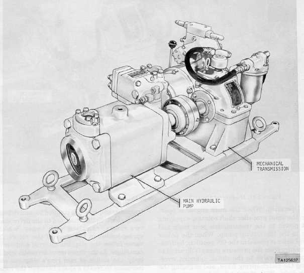
d. Mechanical Transmission and Main Hydraulic Pump Assembly.
(1) Detailed description. The mechanical transmission and main hydraulic pump assembly (Figs. 1-10
and 1-11) provide hydraulic pressure for powering the winches, hoisting boom and spade. It is mounted in the
rear of the winch compartment,
Figure 1-10. Mechanical transmission and main hydraulic pump assembly - left front view.
Change 2 1-13