TM 9-2350-25634-2
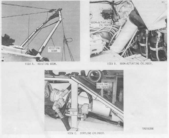
Figure 1-13. Hoisting boom assembly-installed views.
valve held in the STOW position, hydraulic pressure is directed to the back of the boom cylinder; thus causing
the piston rod to extend, raising the boom. Since no pressure is directed to the stayline cylinders, the crank
arms are mechanically moved to their vertical position by the stayline cables, actuating the boom limit valves.
Once the boom is raised, release of the boom safety valve allows the valve to return to its normal live position;
thus retricting the boom to four feet of movement.
(b) Lowering the boom. With the power control valve ON, the boom combination control valve in the
RETRACT/STOW position, and the boom safety valve held in the STOW position, hydraulic pressure is
directed to the rod end of the boom cylinders and bled off the back; thus causing the piston rod to retract and
lower the boom. Pressure is also directed to the back end of the stayline cylinders causing the crank arm to
retract.
f. Main Hydraulic System.
(1) General. The main hydraulic system of the vehicle has three functions: to supply power for control
and operation of the boom; to supply power for control and operation of the hoist and main winches and their
internal brakes; and to supply power for control and operation of the spade.
(2) Hydraulic oil tank (fig. 1-14). Hydraulic fluid from the oil tank is supplied to the hydraulic system,
under pressure, by means of the main hydraulic pump, which is driven by the mechanical transmission.
Through suction, oil passes from the hydraulic oil tank to the main pump and is pressure-discharged to operate
the main hydraulic system.
1-16


