TM 9-2350-256-34-2
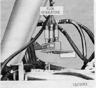
Figure 1-18. Flow regulators
installed view.
g.
Auxiliary Hydraulic System.
(1)
General. The auxiliary system of the vehicle has the following functions: to supply power for control and
emergency operation of the boom; to supply power for control and emergency operation of the spade and winches; and
to supply power for operation of refuel pump and impact wrench.
(2)
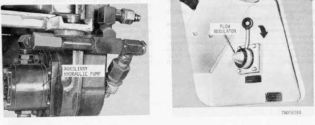
Auxiliary hydraulic pump (fig 1-19). Pressure for the auxiliary hydraulic system is supplied by the auxiliary
pump which is bracket mounted to the auxiliary engine. The auxiliary hydraulic system is engaged by moving the system
selector control handle to AUX and by operating the auxiliary engine (refer to TM 9-2350-256-10).
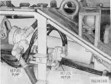
(3) Refuel pump motor (fig. 1-20). A gear-type hydraulic motor drives the refuel pump when refueling or defueling.
Motor rotation is controlled by a four-way selector valve. The refuel pump motor is mounted on the right rear area above
the track in the engine compartment, and is coupled to the refuel pump.
Figure 1-20. Refuel motor and pump assembly
-installed view.
(4)
Flow regulator (adjustable) (fig. 1-21). An adjustable flow regulator is installed in the auxiliary hydraulic system
to provide adjustment of flow for operation of the fuel transfer pump or hydraulic impact wrench. A calibrated dial and
Figure 1-19. Auxiliary hydraulic pump
installed view.
Figure 1-21. Flow regulator (adjustable)
installed view.
1-21


