TM 9-2350-256-34-2
control handle are provided for variable settings. To operate the regulator, move the handle so that the indicator points
to the desired setting. The regulator is mounted on the right rear area above he track in the engine compartment.
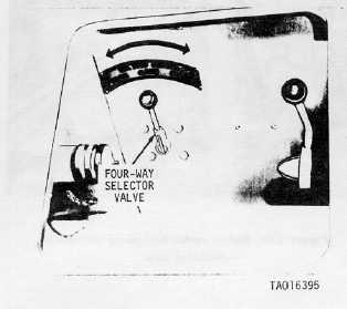
(5) Four-way selector valve (fig. 1-22). A three-position, four-way selector valve is installed in the auxiliary
hydraulic system to control the rotation of the refuel pump and motor. The four-way selector valve is mounted on the
right rear area above the track in the engine compartment.
Figure 1-22. Four-way selector value
installed view.
1-4.
Tabulated Data
a.
Main Winch and Spade Assembly.
(1)
Spade assembly.
Part number
........................................................ 10862159
(2)
Spade-actuating cylinders.
Part number
........................................................ 10867173
(3)
Main winch hydraulic motor.
Part number
........................................................ 11672155
(4)
Main winch.
Part number..................................................................8739010
Manufacturer ...................... Pacific Car and Foundry Company
Model no...........................................................................U-90B
Cable size........................................................25 in Dia. IWRC
Cable length ............................................................
200 ft
Line pull:
Bare drum ................................ ......................... 90,000 lb
b. Hoist Winch Assembly.
(1) Hoist winch hydraulic motor.
Part number ............................................................. .11672155
(2) Hoist winch counterbalance valve.
Part number ............................................................. 10923500
(3) Hoist winch.
Part number..................................................................8739009
Manufacturer....Pacific Car and Foundry Company
Model ........................................................................ .......U35B
Cable size ................................................. ..5/8 diameter IWRC
Cable length .................. .......................................... .......200 ft
Line pull:
Bare drum (4-part line) ................. ..................... .. 50,000 lb
c. Mechanical Transmission and Main Hydraulic
Pump Assembly.
(1) Mechanical transmission.
Part number ............................................................... .8379921
Type ............................... ............................... .single reduction,
.................................................. herringbone, reducer
Ratio ................................. .................................. ......1.265 to 1
Rating
........................ ..................... 150 hp @ 1800 rpm input
.....................................................and 1422 rpm output
(2) Main hydraulic pump.
Part number .......................... .................. ......................7748579
Type ......................... ..............................Vane fixed-displacement
Output (each section):
at 1350-1450 rpm and0-psi ..............................52 gpm (max.)
at 1350-1450 rpm and 2000 psi...42 gpm (min.)
(3) Relief and unloading valve.
Part number ...................................................................10867008
Pressure range............................................ ...............0-2000 psi
d. Hoisting Boom Assembly.
(1) Hoisting boom.
Part number ......................... ................... .. .................... 8676250
Capacity:
Boom .................................. ............. ..... .....................25 ton
Maximum lift height: (center line of hook, vehicle level)
8-foot reach......................................... ............................ 19 ft
4-foot reach......................................... ........................... .22 ft
(2) Cylinder (boom and stayline).
Part number ................................. ........... .....................8743887
Type.................. ............................... single end rod, double-acting
e. Control Valves (Hydraulic Subplate Assembly).
(1) Main winch; hoist winch control value.
Part number ................................. .................................10866877
(3) Power control value.
Part number ........................... .................. . ...................10866876
(4) System selector control valve.
Part number ............................... ............. . ..................10866875
(5) Boom combination control valve.
Part number .............................. ...................................8379908-1
(6) Auxiliary power unit (APLU) emergency winch
control value.
Part number ................................. ........... .................... 11640359
Change 2 1-22