TM 9-2350-256-34-2
(3)
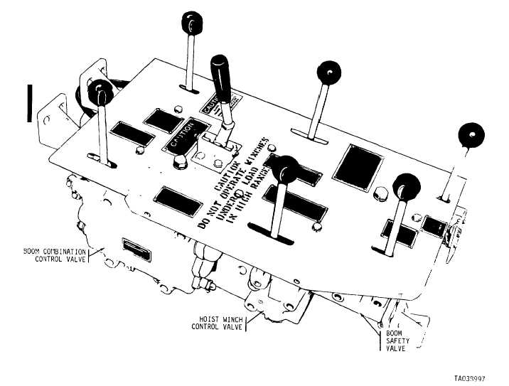
Control valves (hydraulic subplate assembly).
(a)
Detailed description. The hydraulic subplate
assembly or main control panel (figs. 1-15 and 1-16) is
mounted to the right of the driver. Mounted to the subplate
are the main winch, hoist winch, boom safety, and power
control valves; the system selector control valve; the boom
combination control valve, and the auxiliary power unit
(APU) emergency winch control valve. The spade control
handle is installed on the subplate and connected to the
spade combination control valve by a mechanical linkage.
The subplate has numerous ports and passages and
serves as a manifold and mount for the operator's hydraulic
control valves. Bleed valves are installed in the subplate
to provide a means of bleeding portions of the hydraulic
system.
Figure 1-14. Hydraulic oil tank-installed view.
Figure 1-15. Hydraulic subplate assembly
left rear view.
Change 2 1-17


