TM 9-2350-256-34-2
trapped between adjacent vanes as they move past
the inlet chamber. The fluid is then carried along
a path of constant radius to the outlet chamber in
the pressure plate. At this point, the radius of
the cam ring’s elliptical contour decreases, forcing
the fluid into the outlet chambers through pressure
plate ports and through the outlet ports. Pump
output high pressure is directed to the winches and
cylinders to operate them.
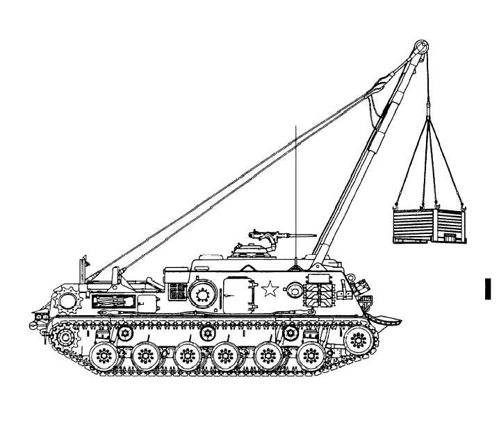
e. Hoisting Boom Assembly.
(1) Detailed description. The hoisting boom
assembly (fig. 1-12) consists of a tubular steel A-
frame, two boom-actuating cylinders, and two stay-
line cylinders. The A-frame, or boom (fig. 1-13),
is installed on top of the vehicle hull and is raised
or lowered by means of controls within the crew
compartment. The boom-actuating cylinders (fig.
1-13) are located within the vehicle on either side
of the crew compartment. They are single-end rod,
double-acting, hydraulic cylinders which extend to
raise the boom and retract to lower it. The two
stayline cylinders (fig. 1-13) are identical to the
boom cylinders and are located at the rear of the
vehicle. They work in unison with the boom cylin-
ders to provide four feet of back-and-forth boom
travel in the raised position.
(2) Operation.
(a) Raising the boom. With the power con-
trol valve ON, the boom combination control valve
in the FORWARD position, and the boom safety
Figure 1-12. Hoisting boom assembly-tight side view.
Change 7
1-15