TM 9--2350--292--20--1
0022 00--7
BATT/GEN GAUGE READS IN YELLOW OR LOWER RED WITH APU
RUNNING AND APU GEN SWITCH ON -- CONTINUED
0022 00
CONTINUED FROM STEP L
1. Reconnect harness 4W700 P1 to APU control
box.
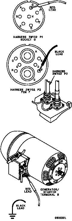
2. Disconnect harness 3W702 P2 from
generator side of APU voltage regulator.
3. Place one multimeter lead in harness 3W132
P1 socket G and other lead on harness
3W702 P2 pin F. Check for continuity.
M
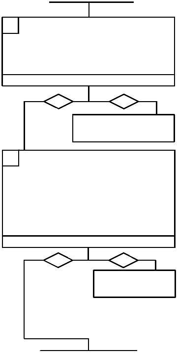
Is continuity present?
Is 0.5 to 5.0 V dc present?
1. Reconnect harness 3W132 P1 to bulkhead
disconnect.
2. Disconnect leads 62 and 66 from APU
generator/starter terminal B.
3. Turn MASTER switch ON, APU GEN switch
OFF, and start APU (TM 9--2350--292--10).
4. Place multimeter red lead on generator/starter
terminal B and black lead to ground. Check for
voltage.
5. Shut off APU and turn MASTER switch OFF
(TM 9--2350--292--10).
no
yes
N
Replace APU generator/
starter (WP 0635 00).
Verify fault is corrected.
no
yes
CONTINUED ON NEXT PAGE
Repair (WP 0290 00) or replace
(WP 0293 00) harness 3W132.
Verify fault is corrected.