TM 9--2350--292--20--1
0022 00--2
BATT/GEN GAUGE READS IN YELLOW OR LOWER RED WITH APU
RUNNING AND APU GEN SWITCH ON -- CONTINUED
0022 00
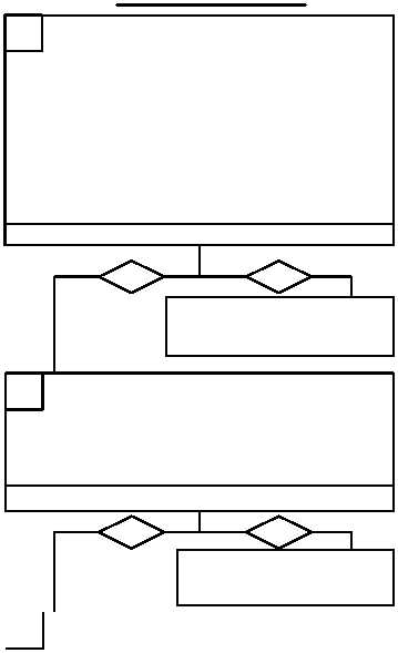
CONTINUED FROM STEP B
Is continuity present?
NOTE
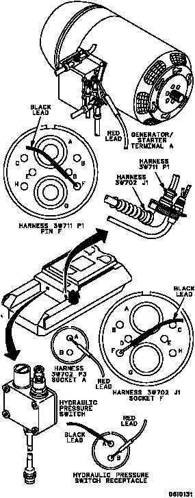
Remove sealant from electrical terminals to
ensure good contact for multimeter leads.
Apply adhesive to all exposed terminals after
troubleshooting is complete.
1. Reconnect harness 3W710 to APU voltage
regulator.
2. Disconnect harness 3W711 P1 from APU
engine disconnect.
3. Place one multimeter on APU generator/starter
terminal A and other lead on harness 3W711
P1 pin F. Check for continuity.
C
Is continuity present?
1. Disconnect harness 3W702 J1 from APU
engine disconnect and 3W702 P3 from
hydraulic pressure switch.
2. Place one multimeter lead in harness 3W702
J1 socket F and other lead in harness 3W702
P3 socket B. Check for continuity.
no
yes
D
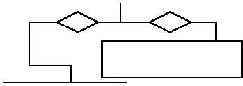
Is continuity present?
1. Reconnect harness 3W711 P1 to APU engine
disconnect.
2. Place one multimeter lead on each hydraulic
pressure switch receptacle pin. Check for
continuity.
E
Repair (WP 0290 00) or replace
(WP 0311 00) harness 3W702.
Verify fault is corrected.
no
yes
Repair or replace hydraulic
pressure switch (WP 0564 00).
Verify fault is corrected.
no
yes
Repair (WP 0290 00) or replace
(WP 0649 00) harness 3W711.
Verify fault is corrected.
CONTINUED ON NEXT PAGE