TM 9--2350--292--20--1
0332 00--4
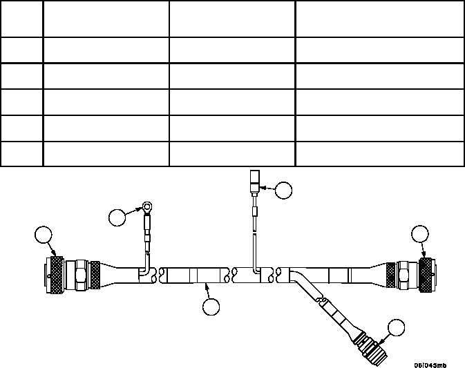
WIRING HARNESS 4W700 REPLACEMENT -- CONTINUED
0332 00
Installation--Continued
NOTE
The following legend identifies attachment points for each
connection.
2. Install wiring harness 4W700 (1) with attaching hardware, at the following attachment points:
Item
No.
4W700
Connector/Lead/Wire
To
Connector/Lead/Wire
Component
Location
6
Connector P2
Crew/Engine Compartment
Bulkhead Connector J4
Crew Compartment
(Rear Left Side)
5
Connector J1
Wiring Harness 4W101 Con-
nector P3
Crew Compartment
(Rear Left Side)
4
Wire 17
Riggers Light Switch
Crew Compartment
(Rear Wall)
3
Wire GND
APU Control Box Mounting
Screw
Crew Compartment
(Near Hoist Winch Cable Chute)
2
Connector P1
APU Control Box
Crew Compartment
(Near Hoist Winch Cable Chute)
Figure 145
1
2
3
4
5
6
NOTE
FOLLOW--ON MAINTENANCE:
Install subfloor plates #19, #24 and #25
(WP 0454 00)
Install storage rack (WP 0463 00)
Install left side air cleaner (WP 0208 00)
Install hydraulic control panel (WP 0245 00)
END OF TASK