TM 9--2350--292--20--1
0005 00--2
THEORY OF OPERATION -- CONTINUED
0005 00
ENGINE -- CONTINUED
The engine’s fuel system primary and fuel/water separator--type secondary fuel filters have top--mounted bleeder
valves to assist in the removal of air from the fuel system. Water is removed automatically by a constant bleed ori-
fice in the primary fuel filter and an automatic water drain in the fuel/water separator filter.
The forced--feed engine lubrication system consists of three circuits: the scavenge circuit, the main or pressure
circuit and the piston cooling circuit. Each circuit is operated independently by one oil pump which consists of four
separate pump sections.
The engine crankcase is vented by the crankcase breather system which exhausts through the crankcase breather
tube at the left turbosupercharger exhaust outlet.
The engine is equipped with two intake manifold heaters which are installed in the air intake system between the
intake manifold elbows and the turbosuperchargers. The heaters, when operated, preheat the air entering the cyl-
inders to facilitate cold--weather starting and cold--weather idle operation.
The engine is equipped with a 650--amp, 28--V dc generator and a 24 V dc solenoid--operated starter.
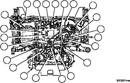
1 Smoke generator manual fuel
shutoff valve
2 Front crankcase breather tube
3 Fire extinguisher tube
4 Speed governing solenoid
5 Oil filter bypass valve
6 Manual fuel shutoff
7 Fuel pump assembly
8 Primary fuel filter
9 Oil pressure warning switch
10 Oil pressure gage transmitter
11 Oil pressure regulator valve
12 Fuel check valve (Fuel back-
flow valve)
13 Damper housing oil drain valve
14 Power takeoff coupling
15 Cylinder head oil drain tube
16 Manifold heater fuel filter
17 Manifold heater fuel solenoid
valve
18 Oil cooler bypass valve
19 Oil sampling valve cock
20 Engine oil cooler thermostatic
bypass valve
21 Oil filter
22 Fuel/water separator
1
2
3
4
5
6
7
8
9
20
10
11
12
13
14
15
17
16
18
19
21
22