TM 9--2350--292--20--1
0005 00--6
THEORY OF OPERATION -- CONTINUED
0005 00
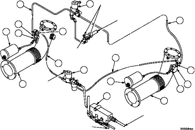
MANIFOLD AIR INDUCTION HEATER SYSTEM
The intake manifold tubes (1) equipped with electrical intake manifold heater ignition units (2) distribute heated su-
percharged air into each bank of cylinders. These air heaters (3) assist engine starting during cold weather.
Operation of the heater switch energizes the manifold heater fuel inlet solenoid valve (4) to allow fuel flow to the
heater nozzles (5). The heater switch also energizes the ignition units (2) to create an electrical spark in the man-
ifold tubes (1), thereby igniting the sprayed fuel.
A leakoff line (6) prevents nozzle fouling and is routed into the fuel injector fuel return line. The fuel is burned in the
intake manifold tubes (1) by the ignition of the heater spark plugs (7) which flame heats the incoming air. This
flame--heated air and the products of combustion flow directly into the cylinders.
The check valve (fuel backflow valve) (8) ensures the necessary fuel pressure to operate the flame heater nozzles
(5). An inlet solenoid valve (4) and fuel return solenoid valve (9) close the flame heater fuel lines (10) when the
flame heater switch is off.
The manifold heater fuel return solenoid valve (9) is located at the rear of the engine. When the valves (4 and 9)
become energized, the ignition units (2) and heater spark plugs (7) act as a check valve to prevent fuel returning
from the injector pump and nozzles from entering the air induction heater system.
8
FUEL INLET
FROM PURGE
PUMP
FUEL INLET
FROM PRIMARY
FUEL FILTER
ELECTRICAL
CONNECTOR
FUEL RETURN FROM
FUEL INJECTOR PUMP
FUEL RETURN
FROM FUEL
INJECTOR NOZZLES
FUEL RETURN
TO VEHICLE
FUEL TANK
6
9
6
5
3
7
5
10
10
4
1
2
1
2
7
3