TM 9--2350--292--20--2
0384 00--2
BRAKE ACTUATING LINK REPLACEMENT -- CONTINUED
0384 00
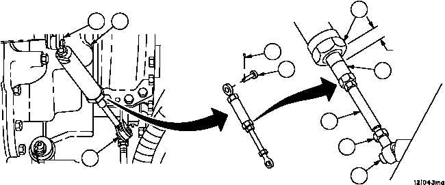
Adjustment
1. Remove cotter pin (1) and headed pin (2), disconnect brake actuating link (3) from air valve linkage (4) on trans-
mission (5). Discard cotter pin.
2. Loosen rod end locknut (6) and turn brake actuating link (3) to adjust free length of brake actuating link (3) until
headed pin (2) can be inserted freely through brake actuating link (3) and air valve linkage (4), with air valve link-
age (4) in release position (down).
3. Tighten rod end locknut (6). Attach brake actuating link (3) to air valve linkage (4) with headed pin (2) and new
cotter pin (1).
NOTE
A mark appears on the brake actuating link plunger, 0.75
in. (19.05 mm) from the edge of the brake actuating link
plunger stop.
4. Apply brakes (TM 9--2350--292--10) and check position of mark (7), mark (7) must align with edge of brake actuat-
ing link plunger stop (8).
5. Loosen brake actuating link locknut (6) at brake linkage (9) and adjust brake actuating link (3) until marks (7) and
(8) align. Tighten brake adjusting link locknut (6).
Figure 163
1
2
4
5
9
0.75 INCH
(19.05 MM)
8
7
3
6
9
NOTE
FOLLOW--ON MAINTENANCE:
Install engine deck assembly (WP 0417 00)
Lock vehicle brakes (TM 9--2350--292--10)
END OF TASK