
TM 9-2350-256-34
0033 00
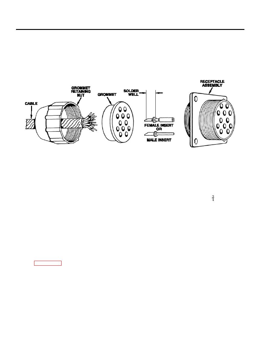
(5) Receptacle assembly:
(a) Strip cable insulation equal to depth of solder wells of inserts.
(b) Pass cable ends through grommet retaining nut, and grommet; insert into solder wells of inserts and
solder (refer to TB SIG 222).
(c) Slide grommet over inserts and press into shell assembly until seated.
(d) Thread grommet retaining nut to shell assembly until seated.
Assembly
1.
General. Continuity checks are performed during the fabrication procedure. The following step provides procedural
instructions for step-by-step assembly and for splicing and wrapping. Refer to REPAIR paragraph above for instructions
for assembly of connectors to cables.
2.
Procedure:
a.
Using the pattern of the old harness, cut new cable to the required lengths and complete all splices. Spliced cable must
be adequately insulated and the insulation must be sealed to the insulation of each cable. Wrap with -in. black plastic
sheet tape-type insulation or use heat-shrinkable promolded covers when available.
b.
Make a continuity check of each cable and splice, using a mulitmeter.
c.
Assemble connectors to cables as identified in DISASSEMBLY paragraph above.
d.
Make another continuity check between opposite ends of cables through the appropriate connector pins.
e.
Wrap splices and wrap cables into harness bundle with plastic electrical insulation tape. Bind cables together with
one-half overlapping turns in the same manner that the old harness was wrapped.
f.
Locate and attach the required circuit number and part number markers using the old harness as a pattern.
Installation
1.
Refer to WPs 0034 00 thru 0038 00 and TM 9-2350-256-20 for installation instructions of wiring harnesses. The circuit
number of each cable is shown on a metal band attached to the junction of terminal end of each cable. Refer to TM
9-2350-256-20 for a listing of the circuit numbers assigned to the vehicle and for the vehicle wiring diagram.
Test and Inspection
1.
The test of a wiring harness is performed during assembly.
END OF WORK PACKAGE
0033 00-4

