TM 9--2350--292--20--1
0250 00--1
BRAKE STOP LIGHT SWITCH AND EXTENSION REPLACEMENT
0250 00
THIS WORK PACKAGE COVERS:
Removal, Installation
INITIAL SETUP:
Tools and Special Tools
General mechanic’s tool kit (item 1, WP 0717 00)
Materials/Parts
Lockwashers (2) (item 58, WP 0718 00)
Marker tags (item 49, WP 0716 00)
Equipment Conditions
Vehicle parked on level surface with tracks
blocked and brakes released
(TM 9--2350--292--10)
Subfloor plate #16 removed (WP 0454 00)
Battery power disconnected (WP 0256 00)
References
TM 9--2350--292--10
Removal
NOTE
Tag all electrical connections and electrical leads prior to
removal to aid in installation.
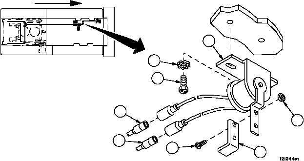
1. Disconnect two circuit no. 75 wires (1) of wiring harness 4W105 from brake stop light switch (2).
2. Remove two screws (3), two lockwashers (4) and brake stop light switch (2). Discard lockwashers.
3. Remove two screws (5), two nuts (6) and extension (7).
4. Inspect parts for damage and replace as required.
Figure 69
FORWARD
1
1
2
3
4
5
6
7