TM 1-1680-320-13&P
0026 00
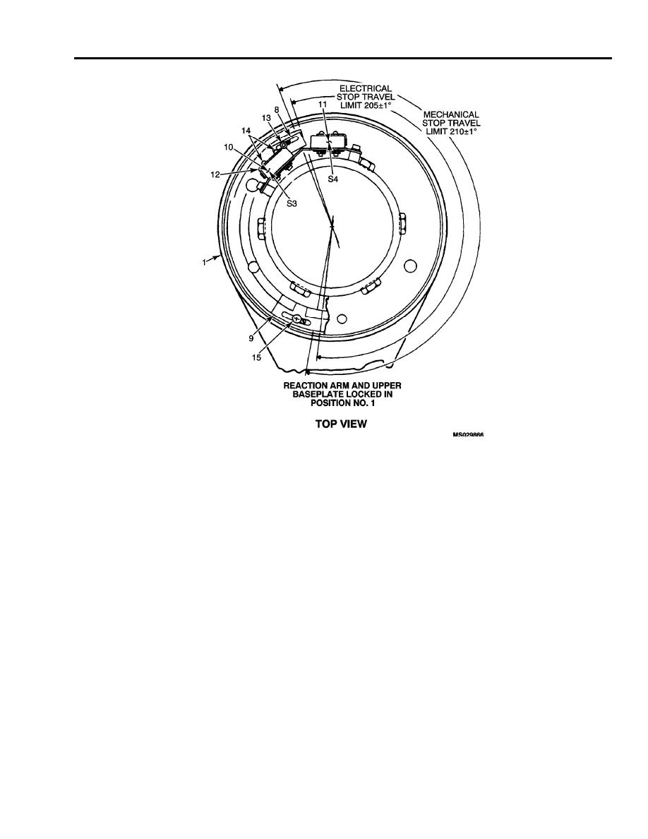
7. Rotate boom head assembly to extreme IN and OUT positions by moving control pendant BOOM IN/OUT
switch to IN and/or OUT positions. Observe locations of switches (10 and 11) at cams (8 and 9) positions.
NOTE
Switches (10 and 11) must actuate before hoist mechanical stops engages.
8. Rotate boomhead to maximum travel OUTBOARD by moving the control pendant BOOM IN/OUT switch to
OUTBOARD position (CCW). Limit switch (10) should stop boom rotation when actuator roller leaf (12) is
depressed by cam (8).
NOTE
Boomhead assembly should be on marked line of STA 82.05. If not, adjustment
is required.
9. Disconnect power.
10. Loosen screw (13) and move cam (8) towards switch (10) for an over-travel condition. Move
cam (8) from switch (10) for under-travel condition.
11. Top of cam (8) should depress actuator and just close switch (10).
12. If required readjust the cam position and secure by applying blue loctite compound to threads of cam screw
(13).
13. Install screw and torque 10-12 in. lbs.
14. Apply power.
15. Move BOOM switch to IN, then OUT positions.
0026 00-5


