TM 5-4240-501-14&P
THEORIES OF OPERATION
Ignition
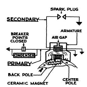
Figure 27.
Fig. 27 shows the flow of magnetism through the iron
core of the coil as the magnet in the flywheel approaches
the armature. The arrows indicate the direction of flow of
the magnetic field. You will notice that there is no (or
very little) magnetism flowing through the upper part of
the core. This is because of the air gap at the top which
causes a resistance. In this position our breaker points
close.
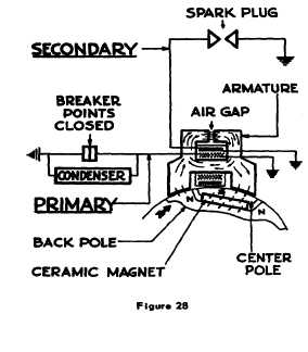
Figure 28.
The flywheel continues to rotate to the position shown in
Fig. 28. The magnetism continues to flow in the same
direction and magnitude through the center of the core
because of primary current. However, the magnetism
flows in an opposite direction through the outer portion of
the core and through the top air gap because of the
change of flywheel position. Since the shunt air gap
provides a path for the flux from the armature legs and
the core, the required current flow through the primary
circuit is low, assuring long breaker point life.
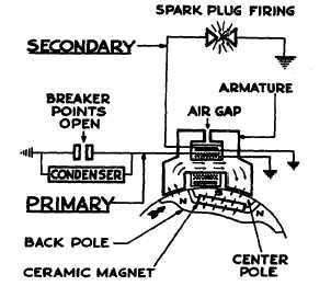
Figure 29.
At this position our breaker points open, the current
stops flowing in the primary circuit and therefore the
electromagnetic
effect
ceases.
The
magnetism
instantaneously changes from the flow shown in Fig. 28
to that shown in Fig. 29. Note the opposite direction of
the arrows indicating a complete reversal of magnetism
which has happened so fast that the flywheel magnet
has not had a chance to move any noticeable amount.
The rapid change in magnetism produces 170 volts in
the primary winding. A voltage is also induced in the
secondary but it is in proportion to the turns ratio, i.e., 60
to 1 or 10,000 volts. This voltage is more than ample to
fire across the spark plug electrodes. This rapid
magnetism change is very short and therefore the flow of
current across the spark plug gap is as long as
necessary, but short enough to afford long electrode life.
Thus we achieve our aims of full power plus long life and
dependability.
15
14


