TM 9-2350-238-10
LOCATION AND DESCRIPTION OF MAJOR COMPONENTS–CONTINUED
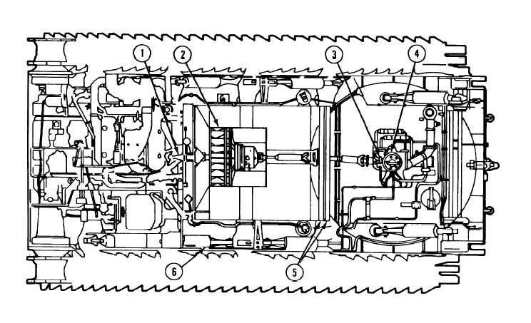
M578 RECOVER Y VEHICLE– TOP VIEW, CUTAWAY
1
2
3
4
AUXILIARY DRIVE. When engine is
operating, auxiliary drive powers
generator, cooling system fan, and (when
magnetic clutch is engaged) hydraulic
pumps.
FAN. Fan forces air through powerplant
compartment and radiators to cool engine.
HYDRAULIC PUMP. Two hydraulic pumps
provide hydraulic pressure when engine is
operating and magnetic clutch is engaged
to. power all hydraulic components.
SLIP RING. Cab electrical system is sup-
plied 24 V dc power from hull electrical
system through brushes and contact ring
on top of hydraulic pump slip ring.
Hydrualic oil from reservoir is supplied to
hydraulic pumps and pressurized hydraulic
oil is supplied to cab through slip ring.
5 TORSION BAR. Each wheel is suspended
by a torsion bar that acts as a spring.
6 LOCKOUT CYLINDER. Each lockout
cylinder acts as a shock absorber, bump
stop, stabilizer, and suspension lockout
device. Vehicles have eight lockout
cylinders. (Lockout cylinders are not
mounted on third from front road wheels
)
1 - 10