2
3
4
Make sure MASTER switch is OFF
before repairing electrical com-
ponents. Failure to observe this war-
ning could result in injury to
personnel.
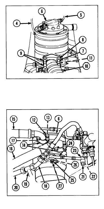
Disconnect two electrical leads (4 and 5)
from top of pump and slip ring assembly
(6).
Remove four hexagon capscrews (7),
four Iockwashers (8), and two split
clamps (9).
Remove metal hose assembly (10) and
preformed packing (11) from pump and
slip ring assembly (6). Cover metal hose
assembly opening.
TM 9-2350-238-34-2
5 Remove eight hexagon head capscrews
(12), eight Iockwashers (13), and four
split flange clamp halves (14) from pump
and slip ring assembly (6).
6 Remove two nonmetallic hose assemblies
(15 and 16) and two preformed packings
(17) from pump and slip ring assembly
(6). Cover hose openings.
7 Disconnect metal tube assembly (18)
from tube tee (19) on pump and slip ring
assembly (6). Cover metal tube assembly
opening.
8 Disconnect hull return line nonmetallic hose assembly (20) from tube tee (19) on pump and
slip ring assembly (6). Cover hose assembly opening.
9 Remove hex nut (21), Iockwasher (22), and screw (23) and disconnect bearing rod end (24)
from cab wall.
10 Remove hex nut (25), Iockwasher (26), and screw (27) and disconnect bearing rod end (24)
from welded bracket on pump and slip ring assembly (6).
2-263


