TM 9-2350-238-34-2
NOTE
l When cab assembly is removed or installed in a maintenance shop, position vehicle in
an area with minimum ceiling clearance of 20 ft (6 m).
l Removal of the cab assembly can be performed using a second M578 Recovery Vehicle
or an M88A1 Recovery Vehicle. Both vehicles must be positioned on a hard surface
with spade down to remove or install the cab assembly.
15 Lift cab assembly (33) straight up and free of hull. Place cab on wood blocks.
INSPECTION/REPAIR
1 Inspect for broken, damaged, or missing parts.
2 If plain bearing unit or outer race assembly are broken or damaged, refer to page 2-269.
3 Repair is by replacement of authorized parts (TM 9-2350-238-24P-2).
INSTALLATION
l
l
1
2
3
Use hoist and chain slings of 30,000
lb (13,620 kg) minimum lifting capa-
city to avoid injury to personnel or
damage to equipment.
NOTE
Prior to installing cab assembly,
refer to page 2-269 for servic-
ing the plain bearing unit and
outer race assembly.
Ensure center of gravity is ob-
tained when positioning sling
and hoist. Approximate center
of gravity can be obtained by
alining the hoist with the center
of left side cab swinging metal
door and right side cab vehicle
hatch door.
Attach sling to hoist and take up slack to
make sure lift is equal at all pressure
points.
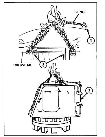
Using a sling and hoist of 30,000 lb (13,620 kg) minimum lifting capacity, connect sling to
crowbar and lifting eyes (1) on top of cab assembly (2).
Insert crowbar in boom hinge pin upper sockets (3).
2-265