TM 9-2350-256-20-2
0202 00
9.
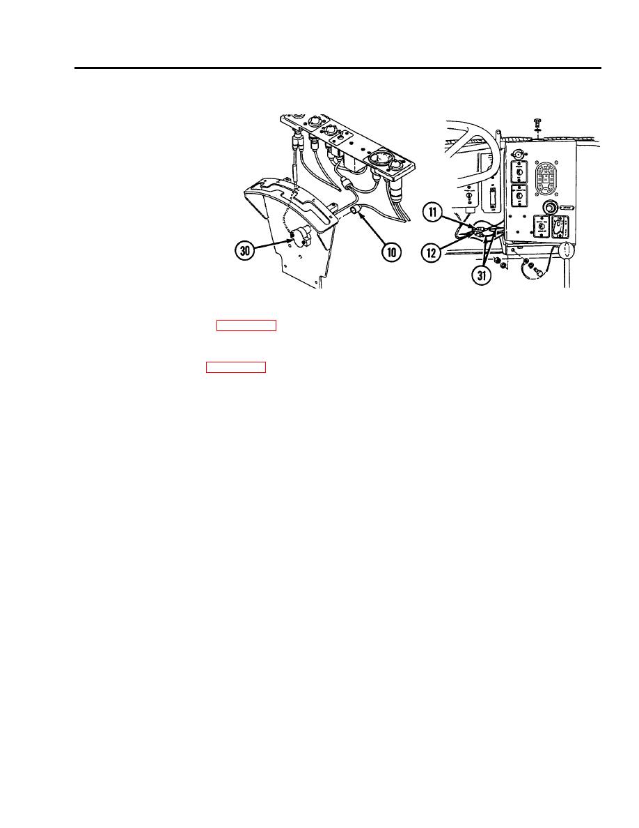
Disconnect connector (10) from red flasher circuit breaker (30).
10. Disconnect connectors (11 and 12) from switch panel to gage panel and miscellaneous switches wiring harness (31).
Disassembly
1.
Disassemble wiring harness (see WP 0255 00 thru 0264 00, as appropriate).
Assembly
1.
Assemble wiring harness (see WP 0255 00 thru 0264 00, as appropriate).
Installation
1.
Connect connectors (11 and 12) to switch panel to gage panel and miscellaneous switches wiring harness (31).
2.
Connect connector (10) to red flasher circuit breaker (30).
3.
Install ground lead (9) to hull (27) using lockwasher (29) and screw (28).
4.
Connect connector (8) to communication system (26).
5.
Connect connector (7) to communication system (25).
6.
Install ground lead (6) to hull (22) using lockwasher (24) and screw (23).
0202 00-5


